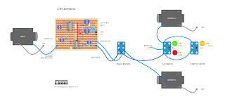
I recently tried building an ABY box with isolating transformers on the outputs, and I just could not get it to work (well, everything worked, apart from the constant buzzing that I could not get rid of, which was incredibly frustrating).
I then pulled out most of the components, just leaving the switching and LED indicators, which worked without any buzzing; however, I did want a phase switch, which brings me to this.
It's a simple opamp buffer running on a dual rail supply for ample headroom, and it also has an inverter to flip the phase of channel B if required, or maybe you just like the sound of out-of-phase amps.
Any dual opamp can be used, and if you only have 7660 instead of 1054 for power inversion, just remove the cut between pins 1 & 8. If you feel uncomfortable about the lack of a capacitor on the buffer's input, there's room to add one - I'm sure you can see where and how.
If you have two amps and no switcher, you're really missing out - buy or build one.

Hi There,
ReplyDeleteso i built this, and the A B and Y switches work really well, no popping noises or anything! So thanks!
But i ran into trouble with the phase inverter on channel 2, when i change the phase, the output 2 completely disappears, no signal at all on channel 2. This also happens on channel 2 by itself, as well as when in the Y configuration. Channel 1 remains unaffected throughout.
I have checked my wiring all ok, all the jumpers, cuts, and components on my vero board - all ok.
there is voltage to the TL072, and there is output voltage from the LT154. What could i be overlooking?
Have you run into this with this circuit?
Thanks in advance,
Lee
Hi Lee
DeleteHave you tested the inverter on its own? So just run signal into the op amp and straight out. If that works, then it’s the switch.
Good luck
HI Andy, I did do that, and it was good. So i checked the switch as well, and that was good as well.
ReplyDeleteI did get everything to work though. What i found was that the inverter out line should be on column 18, row 11 instead of row 10 as that is the output of the TL0172. Thanks!
Lee
So you bypassed the 10u cap on the output?
Deletei guess so...lol
ReplyDeletenot sure why the inverted signal doesn't come through the cap. i checked the connections and it should but it doesn't. i'm going to use an audio probe to see if that help to diagnose.
Yeah that is weird. Really uncommon, almost unheard of, but could it be a dead cap?
Deleteso Eureka!
ReplyDeletei took the cap out, checked it - it was ok, but replaced it anyway. same result (not bypassing the cap of course) :(
however, the strip on the board was the culprit!
there was no continuity between the cap and the inverter out! really strange because it looked okay...so i put a jumper across from the cap to the wire and voilà :) works like a charm!!
thank you for your help and patience!!
Satisfying to sort out unusual problems like this. Glad you have it running as it should.
DeleteHi There, How much Vpp input signal can this circuit pass through TL072 without clipping?
ReplyDeleteHi Artem - it should have incredibly high headroom. The opamp is running +/- 9 volts which allows for a max pp output of about 15volts. Given this is a buffer, Vin should match Vout.
DeleteHi, I assembled it and it works great. Thank you!
Delete