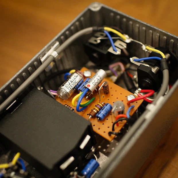
I’m surprised I had not covered this one before, but I suppose it is a MKI, so it should feel fairly familiar.
There seem to have been a few different iterations — essentially just different flavours of the MKI, so keep that in mind when choosing transistors and biasing the circuit. Some versions also used the more familiar point-to-point MKI style board.
Basically it cuts the output limiting resistor in half, from the stock 2.2 Meg down to 1 Meg. The first batch of the new 2015 1965's that went to Joe all had approx 1.5 Meg limiting as stock and the Super Zee bypassed it entirely.
Also worth noting from another post: What no side switch? This is correct. It was making my tuning of the pedal a little erratic at times.
I have not listed transistor types, because they varied, and the chances of you having the exact same transistors D*A*M used — and for them to sound great in a MKI anyway are fairly small. Even from reading posts on the D*A*M forum, Dave appears to have moved away from using 2 x OC75s in this circuit because they were less stable than other options - and you can be pretty sure that D*A*M has a larger selection of transistors to choose from than you or I.
So this looks like one of the D*A*M one-offs from back in the day - a MKI style fuzz, using a variation on a Zonk layout. There are some departures from stock values, some of which are not entirely clear.
There are a few components that are not visible, but if you have any build experience, you can make some reasonable assumptions. Pop it on a breadboard... I know that's what I'm about to do.
One thing that throws me is this - the resistor next to the OC45 (the Q2 collector), is it brown green red gold, (1k5) or purple green red gold (7k5)? I think 7k5, the schematic on FSB says 1k5.
On the breadboard, 7k5 works just fine, so I'll stick with what I see and hear. Can't always trust what you find online, including here ;-)
Just a little fuzz face variant from D*AM - the Maggot Brain from 2019. There are some more recent variations on this as well. Could not see the cap and pot values, so just a partial trace. Being a fuzz face, you kind of know what they might be. I mostly breadboard before building a fuzz face cause they are so small, so I'm really just taking advantage of the form factor of the layouts at times.
There's also a version using BC109 transistors, with a different bias set-up. 33k on Q1-C and 5k9 on Q2-C. Some Maggot brains have a 15n output cap.
Since I'm doing boosters at the moment - the D*A*M Supa Rooster.
I'd suggest placing a 1m resistor on the input and output if you get switch pop - a lot of people do this all the time for their rangemaster type circuits. If you want it to look true to the original, use 1/4w metal film resistors and sneak them under the board.
Pretty much the same layout as the D*A*M pedal, can't see the value on a few components, but safe to say, that anything in the normal area of a rangemaster will be just fine. I'm talking pot values and the smaller input capacitor in particular.
The D*A*M Drag n Fly DF-05 is a hybrid fuzz pedal that combines silicon and germanium transistors, drawing inspiration from the classic Fuzz Face design.
What sets it apart is its unique filter control, located at the input of the circuit. This control blends the input signal between a 10uF and a 4n7 capacitor, offering a wider tonal range compared to the traditional 2u2 found in standard Fuzz Faces. Its brethren the Dragonfly DF-06 has the tone control at the end of the circuit, using something similar to a MKII.
While the overall circuit is straightforward, it incorporates some non-standard component values to fine-tune the sound, and there's a touch of the Vox Tone Bender in some circuit variations - and there were many variations on this circuit.
D*A*M DRAG N FLY DF-05 VERO LAYOUT
This is one of the layouts used by D*A*M - the 0 ohm resistors are often replaced by jumpers under the board.
Looking at the image below, it appears that they used velcro to mount the circuit to the back of the pots.
SCHEMATIC / LTSPICE
Component values have differed across various production runs over the years. The schematic serves primarily as a guide, illustrating the circuit's topology rather than providing definitive values.
Anyone familiar with D*A*M circuits will have seen the input capacitor blend on a few other designs.
This is what the signal looks like at the base of Q1. Basically it sweeps the bass response from thin to fat. The small bump in the middle is a result of the 47pf cap across the collector and base of Q1.
VARIATIONS
There are so many… check the D*A*M forum post hereThese are just some that I've seen; there are probably more. So if you don't have the "right" transistors, maybe don't stress about selection too much, as a lot were used over time.
10k instead of 18k resistor on Q1 collector (likely to be transistor selection related)
2 x trimmers for biasing on some layouts
56k resistor instead of 120k between the base of Q1 and the emitter of Q2
10uf and 3n3 on the input blend
R1 / 1 meg resistor on the input, not always used
Q1: BC108, BC107B and plenty more unidentified silicon transistors
Q2: AC176, AC187, OC76, OC82, AC128, CV7112, OC140 (note some are PNP)
note: this is a revised post from April 2022 with updated information, schematic and layout.
This the D*A*M Dragonfly DF-06, which is somewhat confusingly not the same circuit as the D*A*M Drag n Fly. They're both in the Fuzz Face family, but they each approach the tone control differently. The Drag n Fly does the tone shaping up front, while the Dragonfly does it at the end of the circuit, using a method similar to a MKIII.
Not having one available to trace, I’ve relied on photos available online. Unfortunately a few capacitor values can't be seen, however, on the upside, it's not hard to guess what they might be to get something very close to the mark.
For me, the key value is the capacitor forming a high-pass filter in the tone section. Breadboard it and see what you like, or be prepared for a bit of soldering on the vero board. The other caps certainly have a role to play, my feeling is that while they contribute to the overall bass response, the filter section is where the magic happens.
Possible high-pass filter values:
24k 4n7 1.3khz
24k 3n3 2khz
24k 2n2 3khz
D*A*M DRAGONFLY DF-06 0.15" VERO LAYOUT
DRAGONFLY TRANSISTORS
It's a hybrid silicon / germanium circuit. The DF-06 below uses a BC337 & an OC141. The BC337 is very similar to a 2N2222A which us a regular low gain NPN transistor. Just watch the transistor pinouts, as the BC will be the reverse of the 2N. i.e. Flipped 180 degrees.
If you don't have any decent NPN germanium transistors, drop in a silicon and I'm sure it will still work - but you may need to tweak some resistor values to get it to work well. This may even be the case with germanium transistors, as I’m sure Dave Main will have biased this to get what he wanted out of these particular transistors.
STYRO CAPS
As you can see, the styro cap (the silver one) on the input to ground is larger than the one in the high pass filter section, which leads me to believe that it's probably a 10n, similar to what might be found on a MKII Tone Bender.
D*A*M DRAGONFLY SCHEMATIC
As a few values are not known, this is really just a guide to what the circuit looks like and it's handy for me to test possible values in LTspice. Where values are unknown, I think a safe bet is running with component values used in fuzz faces and tone benders. Seems like an obvious choice. An AC127 was used in LTspice, as I didn't have access to the model for an OC141.
Like most things pedal-related, and I've mentioned this before - nothing beats building it and testing values on a breadboard.
INPUT CAP C2
I've shown a few values below, which as mentioned above, are probably common fuzz face or tone bender values.
TONE CONTROL - HPF CAP C4
C4 forms a high pass filter with R6, the 24k resistor to ground. The high pass filter is mixed in with a direct signal from Q2 via C3 (100n cap). This is quite similar to a MKIII Tone Bender arrangement.
Lower value = more mids. Higher values have a bit more sizzle.
Not much around in terms of video - this is all I could find
I probably should start by saying that this is not a full trace, as I do not have one in my possession. However, you can put a lot together based on photos online. Mainly on the D*A*M forum here and via some reverb listing that show some different angles.
The first three stages don't appear strange, but it get's pretty weird at the end, so I'm not sure if I have everything right around the tone control (which has the worst views in the photos) - it looks OK on LTspice, but I do need to get it on the breadboard. The fuzz control is unlike anything. that I've ever seen before, and the tone control is equally weird.
If it works, I'll put a layout together. The D*A*M layout follows the original from what I can see, but much neater and less chaotic.
Reverb listing photo
More reading can be found here, on the Tone Machines blog - there are multiple versions of the Fuzzmaster, some with two transistors, some with two knobs. The D*A*M Fuzz Supreme is the first from the Fuzzmaster series - the Wildcat and MKIV followed this one.
Following on from the previous post, this is the D*A*M version of the Colorsound Fuzz Sound. Thread on the D*A*M forum can be found here. Basically take a D*A*M Fuzz Sound, and change the Fuzz pot to an internal trimmer.
Unlike the regular Park 2 knob with a large 25u coupling cap between the darlington pair and Q3, D*A*M has stuck with the stock 220n cap. However, the cap from the emitter of the darlington pair to ground has been increased, which provides a bit of a bass boost. There's also the bigger caps in the filter section, often used by Dave Main, which is also my favourite set-up. It just drops the cut-off of the high pass filter on the treble side down and helps with the bass response. It also has a smaller resistor between the tone and volume pot.
So despite the smaller coupling cap, this has been accounted for elsewhere.
The El Diablo... A Dave Main creation, part Sola Sound MK1.5 Tone Bender / part Vox Tone Bender - hence the MK1.75 moniker. And why El Diablo? apart from the colour, this thing sounds mean as hell.
They appeared to use a couple of different transistors for Q2, but the OC75 remains up front - the OC75 definitely provides a sonic signature in a circuit like this. The version I saw with the OC84 transistor has a small silva-mica cap between the collector and base of Q1 (I couldn't see the value).
From the Vox:
smaller input cap
smaller Level pot
a resistor placed between the Attack pot and ground
resistor values
OC76 for Q2
From the MK1.5:
10n output cap (although some Vox carried this)
and of course, the OC75 for Q1 is pretty important
SOLA SOUND MK1.75 'EL DIABLO' TONE BENDER - 0.15" VERO LAYOUT
So to get something sounding like the video below from pinstripedclips, I needed to use a relatively low gain transistor ~50hfe for Q1 and in some cases the D*A*M dirty hippie mod, often employed to help bias an OC75.
I added the video below, as this is much closer to what I was getting on the breadboard with most of my transistors. Also worth noting as mentioned by Phil in the comments, pinstripedclips has a fairly specific set-up, and who knows how that contributes.
Someone mentioned this in the comments recently (thank you ClassicFuzz), so I thought I'd have a look at the photos on Reverb.
The Goldie is a MKI in a MKII enclosure from March 2022, likely to be inspired by this unit found in Germany - which is an absolute train wreck of work.
It looks a lot like a MKII board, it even has a cap to ground on the input - a full set of OC82 transistors is also more likely to be seen on a MKII. That’s about where the differences end - a nice nod to a MKII, but it’s definitely a MKI.
This Goldie should not be confused with the other Goldie, which is a MK1.5 - confusing no?
SOLA SOUND / D*A*M GOLDIE MKI TONE BENDER - 0.15" VERO LAYOUT
Apart from construction, the most obvious difference to a regular MKI is the cap to ground on the base of Q1 (the silver polystyrene cap). I haven't been able to spot the value anywhere - thought I could vaguely see an n3 on one, meaning that it might be a 3n3 or similar low-value cap. D*A*M have used a 3n3 on the input of some MKIs in the past, so probably a safe bet that this is the same.
I also haven't put eyes on the value of the brown box cap, which is most likely 100n (standard value). Same for the input cap, I'm assuming 10n as a standard value, but you never know.
Below is the version with the extra resistor in parallel with the 470k which would change the biasing of Q2. It also appears to have a 47k resistor instead of a 56k resistor on the output. 47k vs 56k makes very little difference. A slight change to the HPF that it forms with the 100n cap, but not much to worry about (34hz vs 28hz respectively). There's probably a similar range of variance just with normal component tolerances.
This is a standard germanium Fuzzrite with a 250k depth pot instead of a 350k. I found the old layout while doing a clean-out and a correction and realised that I had not posted the 0.15” version.
The layout is a copy of the D*A*M design - mind you, I’ve never actually seen the value of the blue caps, so there’s an assumption that these are 2n2 caps. Like anything produced by D*A*M - expect a solid guitar effect at the end of the build.
It's a Tone Machine / Arbiter Doubler - let's get that out of the way up front. Here's the thread on the D*A*M forum for the Grand Magnus Orbiter
Rainy day project for me, as I already have a Tone Machine that I'm happy with. Not sure I'd ever be up for a two-layer tagboard layout… The D*A*M Grand Magnus Orbiter is something special in that regard.
This is also an incomplete trace as the second tag board is not visible - which also happens to include the tone control. I'd be surprised if Dave Main didn't tweak it somehow. Personally, I think a larger cap in the tone stack to increase mid-range might be a distinct possibility - not unlike tweaks made to his Fuzz Sounds for a beefier sound.
The only significant change I noticed on the top board is the 10u cap on the emitter of Q, so it's a bit hotter at the start. Silicon diodes are used on the top board in the octave section, which usually provides better (or at least different) results to germanium.
I'm assuming that if anyone builds this, they'll be an experienced builder, so I've left a few things that I might normally include off the layout.
D*A*M GRAND MAGNUS ORBITER - TAG BOARD LAYOUT
Photo care of Reverb.
Looks like 100k sustain pot
LTSPICE
This is the difference with the 10uf cap on the emitter of Q1 - basically, things get square right from the start, and there's an increase in level and a slight change in the frequency response.
Now we see the response at the output - assuming stock values were used on the Grand Magnus Orbiter. As mentioned earlier, I'd be surprised if this was left stock, and like the Big Muff, the Tone Machine tone control is easy to mod and shape to your taste. A standard mod is to increase the size of the 3n3 capacitor to lift the mid scoop. Even a small increase to 4n7 makes a difference. Another mod is adding a 22k resistor after the 3n3 capacitor, which makes it much more like a BMP tone control and dramatically increases the scoop.
This is the bass and treble sides of the tone control.
A full description can be found here, which is the tagboard layout. I built mine on tagboard, but that isn't for everyone, so the standard vero layout is below.
So I just worked out why I purchased some Motorola MC1748CG tin can op amps - it was to make one of these. I've had them in my parts draw for a while, trying to remember what they were supposed to be for. I thought maybe the Hudson Sidecar, but no, I need a dual for that.
Anyways, here it is, and I may refine this a little more at some stage or post something smaller on regular vero, as this is really for my own purposes - I doubt anyone else will want to make this at this size using these op-amps. I almost did the full-size one on tagboard, but that was even bigger.
D*A*M EZEKIEL 25:17 LOW-FREQUENCY DISTORTION GENERATOR - VERO LAYOUT
This is as close as I could get to the original layout for the D*A*M Sonic Titan. It's pretty much a JFET smashing the LM386 with level, but in the nicest possible way. I've read a 10k level pot can brighten things up a little. Apparently, this was on some of the earlier versions.
There's also a bit of discussion around how the tone control functions and interacts with the level control, resulting in the third layout below, using the Sonic Samurai mods. Other issues include DC causing crackle down the line (no cap on the input to the FET) and 386 note decay issues.
D*A*M SONIC TITAN - VERO LAYOUT
The original used a 2N3819 JFET - I've listed a J201 as it's the same pinout as some other common FETs, and I have a few and like the sound.
Notice any similarities between the layout above and the circuit from the datasheet below? David Main from, or who is D*A*M, mentioned that the Sonic Titan is a couple of circuits jammed together. One is straight frodatasheet sheet, and the other is a standard JFET boost.
While I was thinking of what could be made with tag board off-cuts, this popped into my head.
The D*A*M Red Rooster Booster is probably my all-time favourite booster - I've only ever made one, and it was so good I stopped there (it was a point-to-point npn version with trimmer).
This is a PNP version; the 3k9 resistor could be swapped for an upright/inline trimmer.
D*A*M RED ROOSTER BOOSTER - TAG BOARD LAYOUT
Fun fact: In Australia Red Rooster is the name of a cheap roast chicken franchise.
As far as I know, only a handful of D*A*M FZ-678 were ever made, maybe 5 in total - it's a variation on a Zonk Machine. It's the same structure as a Zonk / MKI, but with a filter attached to the input.
I haven't made a layout for it, as it's all there to see - and I could not imagine that anyone wants to build one using this format. If you want to make one, I'd say just use your favourite Zonk layout, and tune the filter to your liking. Like all things Zonk / MKI - get it on the breadboard first.
D*A*M FZ-678
There are still a couple of things I'm unsure about on this, as there are very few photos available, and the colour coding on blue metal-oxide resistors is misleading. example: the 470k resistor looks like 5m7
Link to Stompboxes site. Transistors: Mullard OC42, OC44 and OC83 (Q1, 2, & 3).
Unlike the D*A*M Fuzzrong FR-69, which is very much a straight germanium Fuzzrite, the D*A*M Fuzzrong FR-70 is a little different.
It's a version of the Rosac Nu-Fuzz, which was designed by Ed Sanner, the designer of the Fuzzrite. There are a some changes with component values, but you are basically looking at the bones of Nu-Fuzz.
It uses very common transistors - so there is no hunting for expensive/rare germanium only to find out they sound 95% like the ones you already have...
D*A*M FUZZRONG FR-70 - VERO LAYOUT (ORIGINAL D*A*M LAYOUT)
I altered the layout a little to add a cap for the power supply - also changed the small cap across Q1 to 1n to help reduce noise, and it was a tad bit bright for my liking. It’s a really solid sounding circuit.
NU-FUZZ vs FR-70
This is swapping the tone/depth pots - similar, but the FR-70 has less bottom end.
AND HERE'S A CLIP FROM ONE OF MY YOUTUBE FUZZ FAVES