Such a lengthy heading... I've been waiting to find out what was going on with this one, and it has recently been traced on the Pedal PCB forum. There's also a great back story here, with some info on the Zener diode.
The schematic can also be found via the Pedal PCB link above.
There are other earlier versions, including a PNP version using an OC75. The OC75 version is very close to the OC140 version - although there's no diode involved in biasing the collector, just a 4k7 resistor (and obviously some different transistors on Q1 / Q2). A couple of odd value resistors, like a 10ohm on the emitter of Q2. I'm pretty sure I'm reading it correctly, but...
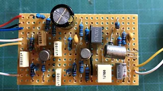
The PCB is a Jumbo Tone Bender board with modified parts/values.
COLORSOUND HYBRID TONE BENDER (2018 EDITION) - STANDARD VERO LAYOUT
It works.... sounds like a Tone Bender too. Not a direct replication of the sound of a MKIII / MKIV, but the flavour is there.
I had to make a few substitutions as I did not have all the parts as per spec.
- 5.1V zener diode, instead of the 4.7V (bear in mind the actual value has yet to be confirmed)
- AC127 instead of the OC140 - it's quite leaky, with a gain around 100
- AT426 instead of the BC107
- 100n instead of 10n, just because I wanted to, and it has been seen in earlier versions
- B25k pot instead of W20k
TONE POT SWEEP
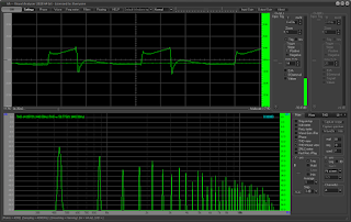
ON THE SCOPE / FFT
Bass


8 comments:
Enjoy the site.
I have been breadboarding this very circuit too. I found the following which might be interesting for you:
1. Change the Q3 collector resistors to bias Q3 collector voltage. I found that around 2.8V sounds good. As the resistor value increases, the voltage falls. The fuzz gets compressed and more velcro-like with a small volume loss. As the resistor value decreases, the tone opens up but at around 3.2V, it starts losing sparkle. I put in a 20K pot to vary the bias with a resistor in series. The resistor in series is there to avoid the "losing sparkle" part of the bias and hence pick a value that allows you to start at say 3.1V.
2. The "Fuzz" knob is only usable for me from 11 onwards and does not seem to be much better than me using my guitar volume when fuzz is maxed. Hence, I removed it. I also removed the 10nf cap.
3. I put in a bass cut circuit at the start to simulate a bass rolloff. Essentially it is a C1M pot with lug 2 to input and lug 3 to the 33k resistor. I also put a 1nf cap across lug 2 and 3. The bass cut helps note clarity and can reduce wool. The removal of the 10nf is then ok because one can dial in same amount of bass cut at the start.
I do not have the OC Ge transistors but I have a bunch of russian NPN transistors which did the trick.
Interesting, and thank you for sharing your work. I'll have to give those a try. I get a decent amount of range out of the fuzz pot, so maybe my Q3 reacts a little differently, or my Q1 / Q2 combo is providing lower gain.
I'm still waiting for OC140s to arrive in the post - any day now....
Is it possible for you to make a vero layout for a pnp germanium transistor version that uses oc75?
I haven’t looked at this one for a while - I’ll see what i can find, or feel free to link to a schematic here
I don't have a schematic. I could only find pictures of hybrid yellow tone bender with oc75 on the internet. I hope you can make a layout of a TB using oc75.
I found the schematic on the same forum thread as the NPN version on pedalpcb. It’s very similar, could make it on the same layout with a few minor alterations.
There seems to be a few variations of this circuit with different cap and tone pot values.
Thank you very much.
I was also able to see the schematic for the oc75 version.
I will start on the oc75 version after comparing it with the layout you have made.
Also interested in this schematic
Post a Comment