Showing posts with label ONE TRANSISTOR. Show all posts

Wednesday, October 26, 2022

LOVEPEDAL: JTM45

A nice easy one - and I'm not sure if anyone has done more versions of an Electra Distortion than Lovepedal has.  But hey if it's working for them and people like it, who am I to judge?   A JTM45 it is not.

LOVEPEDAL JTM45 - VERO LAYOUT

LOVEPEDAL JTM45 - VERO LAYOUT DIY STOMPBOX


Monday, October 17, 2022

RIFT AMPLIFICATION: EL34

It's a single transistor boost, not unlike an Electra.  This pedal is somewhat infamous in the DIY community for exaggerated claims about what it sounds like - although no one in their right mind would question the quality of the point-to-point work in the enclosure that Rift did.    

The Boost switch is normally a foot switch.  Note that the gain control does nothing without the boost switch engaged.

RIFT AMPLIFICATION EL34 - VERO LAYOUT

RIFT AMPLIFICATION EL34 - GUITAR EFFECT VERO LAYOUT


SCHEMATIC & SPICE RESPONSE

It's not much to look at - a bit of boost and dirt at higher settings, low-end is filtered off by the input cap and some highs are taken out with the tone control.  

Schematic redrawn from the Gray Bench trace - check out the youtube channel if you have not already - a lot of good tear-down videos.


VIDEO DEMOS


Thursday, May 12, 2022

JOHN HORNBY SKEWES: Selectatone TB2 Treble and Bass Booster, Tag Board Layout

While on the JHS thing, I noticed this booster and thought it looked interesting.  The output switches between filters to allow for treble and bass boost, unlike most other boosters where it all happens at the input.

Very few seem to be around, as I could only find one photo of the internals and one video demo.  The schematic still has a couple of assumed (but working) values, which are explained below and marked on the layout.

There's a bit of off-board wiring, which is how the original was built - and no volume control.  

JOHN HORNBY SKEWES SELECTATONE TB2 - TAG BOARD LAYOUT

JOHN HORNBY SKEWES SELECTATONE TB2 - TAG BAORD LAYOUT


Image credit: Effects Database https://www.effectsdatabase.com/model/jhs/selectatone#


LTSPICE RESULTS

Both with 100n for the input cap (C1), and the cap linking the treble bass switch (C2).


Changes to the 100n caps (C1, C2) mentioned above have almost no impact on the frequency response of the treble boost (right down to 22n), so tweaking these caps is more around tweaking the bass boost to your liking, and there will be some changes to how it distorts as well.


I split the circuit into two for bass and treble boost, as switches are painful in LTspice - simple SPDT / DPDT switches don't exist.  

For nerdy folks familiar with spice, here's what I was doing (schematic below).   

Short story for lesser nerds, a smaller C5 cap in the bass boost section raises the boost level and shifts it towards the mid-range.  C2 tunes how much low-end roll-off there is.  i.e. you might want a low-mid boost without the flabbiness of too much low-frequency content.

C1 impacts the response, affecting how the transistor distorts, so it's worth trying a 47n in there and a 100n.

Basically, breadboard it and play with C1, C2, and C5. 


Treble boost vs Bass Boost


Input cap variations effect on the Treble Boost output


VIDEO DEMO


OC71 vs 1T308 TRANSISTORS

Spot the difference?  Someone had a question in the comments, so I thought I'd quickly breadboard it for a look - note that this is from the 100n cap on the output, not after the high pass filter.

So turns out they look almost identical, and voltages also measured about the same.   


Wednesday, May 4, 2022

ANALOG MAN: Beano Boost

The Analog Man Beano Boost takes the classic Rangemaster treble booster and adds a very useful function — a switched input capacitor that widens the tonal range beyond the original’s treble boost.

Because it’s a single-transistor germanium circuit, the choice of transistor does shape the tone and clipping character, especially at higher gain settings.  That said, you don’t need to hunt down an expensive vintage OC44 to get great results.  Many germanium transistors will work really well in this circuit — just be mindful of noise, as a bit of hiss is common with older germanium devices.

Quite a bit of info here on Analog Man's website 


ANALOG MAN BEANO BOOST - TAG BOARD LAYOUTS

ANALOG MAN BEANO BOOST - TAG BOARD LAYOUTS


Same again, but with a pot to control the gain - with the 5k pot at around 50% the series resistance is about 3.5k depending on component tolerances.  I think this is close enough to the stock 3.9k - you could use something a bit larger than 1k to get it closer, but it really doesn't make a massive difference.

This is handy for finding the sweet spot for just the right amount of grit in the boost.  Another useful option is to replace the 68k resistor with a pot (100k as an example).  One of the Steve Williams boosters has this addition - minor downside, the pot has DC on it, so it will sound scratchy / crackly.


ORIGINAL BEANO BOOST LAYOUT

This is one of the layouts used by Analog Man.  Note that I've done it in two layers, as it's hard to show parts directly underneath each other in this format.  


IMPORTANT: the mounting points on the strip must be isolated from the enclosure 

VIDEO DEMO


Saturday, January 1, 2022

EARTHQUAKER DEVICES: Bows

The Earthquaker Devices Bows is a straight-up germanium Rangemaster with some modern tweaks.  It uses an NPN transistor and has a switch to swap to a larger input capacitor for a full-range boost.

The space above the transistor on this layout allows it to be mounted on its side (bent over 90 degrees), as OC transistors are pretty tall, and if you use the mounting points, you will need to reduce the height of the transistor in the enclosure.  It's generally a good idea to place insulation on the legs of the transistor so they don't short when you bend them.  If not all the legs, at least the base leg in the centre of the three.


EARTHQUAKER DEVICES BOWS - VERO LAYOUT

EARTHQUAKER DEVICES BOWS - STOMPBOX VERO LAYOUT


Wednesday, November 17, 2021

PETE CORNISH: TB-83 Treble Booster, Point to Point Layout

I followed a vaguely similar layout to the one pictured at the bottom of the post for the Pete Cornish TB-83 Treble Booster.   

This is a straight treble boost using a silicon transistor - it's going to sound horrible into anything apart from a cranked valve amp, or maybe a valve based pedal.  Given this was in Brian May's rig, think normal channel of a cranked AC30, with this hitting it.  Well maybe you aren't running nine AC30s at once, all running so hard the border on catching fire, but you get the idea.


PETE CORNISH TB-83   POINT TO POINT LAYOUT

PETE CORNISH TB-83 - POINT TO POINT LAYOUT


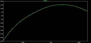
PETE CORNISH TB-83 - LTSPICE

I used the schematic from Fryer Guitars - link here.  

PETE CORNISH TB-83 - LTSPICE


Wednesday, January 27, 2021

DALLAS: Rangemaster, Tag Board Layout

A bit of a classic - well one of the first guitar effects really, the Dallas Rangemaster.  A nice simple one for a quick build using leftover tag board.   

In theory there is room to fit the output cap on the board too, but I liked the straight lines of the components.  
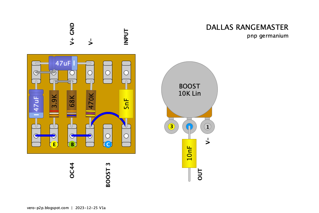

DALLAS RANGEMASTER TREBLE BOOSTER - TAG BOARD LAYOUT

DALLAS RANGEMASTER TREBLE BOOSTER - TAG BOARD LAYOUT


Thursday, January 21, 2021

D*A*M: Red Rooster Booster, Tag Board Layout

While I was thinking of what could be made with tag board off-cuts, this popped into my head. 

The D*A*M Red Rooster Booster is probably my all-time favourite booster - I've only ever made one, and it was so good I stopped there (it was a point-to-point npn version with trimmer).

This is a PNP version; the 3k9 resistor could be swapped for an upright/inline trimmer.  


D*A*M RED ROOSTER BOOSTER - TAG BOARD LAYOUT

D*A*M RED ROOSTER BOOSTER - TAG BOARD LAYOUT


Fun fact: In Australia Red Rooster is the name of a cheap roast chicken franchise.


Sunday, November 8, 2020

D*A*M: Red Rooster Booster

I've already done a point to point layout for the D*A*M Red Rooster Booster (which I love by the way), but as I'm on a run of D*A*M layouts today, I thought I might do this one too.  Like the rest, this is not my layout; it's a close copy of the D*A*M layout.  If you want to stay true to the look, hide the jumper under the board.

This is the PNP version, which can easily be changed to NPN if you prefer by flipping the electrolytic caps.  

I noticed in one photo, a resistor to ground from the 10n output cap.  Maybe there was some pop that needed to be dealt with?   Anyway, squeeze that in between the two electrolytics if you need or want to try that.  I couldn't make out the value...  1meg has worked for me in the past.

Try setting the trimmer to 3.9k to start with, as that's the standard value for a Rangemaster Treble booster, which this of course is a variation on.  Someone once asked David Main about bias voltages - he suggested 6.66v - no doubt a little joke on his part, but it will get you close.  This is one that you can happily bias by ear; it seems fairly forgiving, at least it was on my other build. 


D*A*M RED ROOSTER BOOSTER - VERO LAYOUT

D*A*M RED ROOSTER BOOSTER - VERO LAYOUT


Saturday, August 8, 2020

D*A*M: Red Rooster Booster, Point to Point Layout

A variation on the classic Rangemaster Treble Booster from D*A*M.  The Red Rooster germanium booster uses a NPN transistor so it can run off a normal power supply, and features a capacitor blend on the input to sweep between treble boost and full range boost.

This has a lot of boost on tap - it will crush anything it's put in front of.  It's also happens to sound great, so I'd recommend building it if you have the parts spare and valves to punish.

There's an excellent article here from R.G. Keen as to how a Rangemaster works, including bias voltages and transistor selection.  Electrosmash  also has a very detail explanation.


D*A*M RED ROOSTER BOOSTER - POINT TO POINT LAYOUT

D*A*M RED ROOSTER BOOSTER - POINT TO POINT LAYOUT


NOTE:  Stock trimmer setting is 3k9 for a Rangemaster. 

D*A*M RED ROOSTER BOOSTER - ON THE BENCH

Not exactly parts as per schematic.  I used a 2n7 instead of a 4n7 cap and a 30k trimmer instead of a 5k trimmer as I had a spare sitting right in front of me at the time that I thought I might use instead.

I used an old AC176 NPN germanium transistor with axial and tropical fish caps for added mojo.  It sounds killer, which apart from the additional gain, I think is the AC176 working its magic.    


D*A*M RED ROOSTER ON THE SCOPE

Signal source:  440hz sine wave, approx 130mv TRMS


Range 0%, with a fair bit of boost (can't remember where it was exactly).  There's still more boost available, I stopped here before it started to clip the sound card input on my laptop.


Range 50%, with boost pulled back


Range 100%, still quite a bit of boost left, as mentioned above, I stopped so as to not clip the sound card.  It's getting pretty dirty by this stage, producing a lot of harmonics.