Showing posts with label BOOST. Show all posts

Monday, September 29, 2025

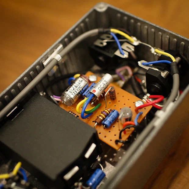
COLORSOUND: Treble Booster, Steve Williams (partial trace)

So there are a few bits missing, but if you are familiar with treble boosters, I'm sure you'll work it out.  Being a small and simple circuit, it's a good candidate for breadboarding.

The filter pot is your standard input blend, probably similar to the values that Steve Williams uses in his Pigdog Competition Special boosters, which is followed by a silicon treble booster with a coupling cap and volume pot attached to the end.  So a little different to a Range Master in that sense.  It's more akin to the Guild Treble boosters

Updated layout:  Thanks Zollinger Analog for pointing out that there is actually a link between pins 1 & 2.   I couldn't see what was right in front of me...  the link is sitting on the other side of the pot.

COLORSOUND TREBLE BOOSTER - STEVE WILLIAMS

COLORSOUND TREBLE BOOSTER - STEVE WILLIAMS

Important to note that this is a partial trace - you may have to test this and work a few things out yourself.

COLORSOUND TREBLE BOOSTER - STEVE WILLIAMS


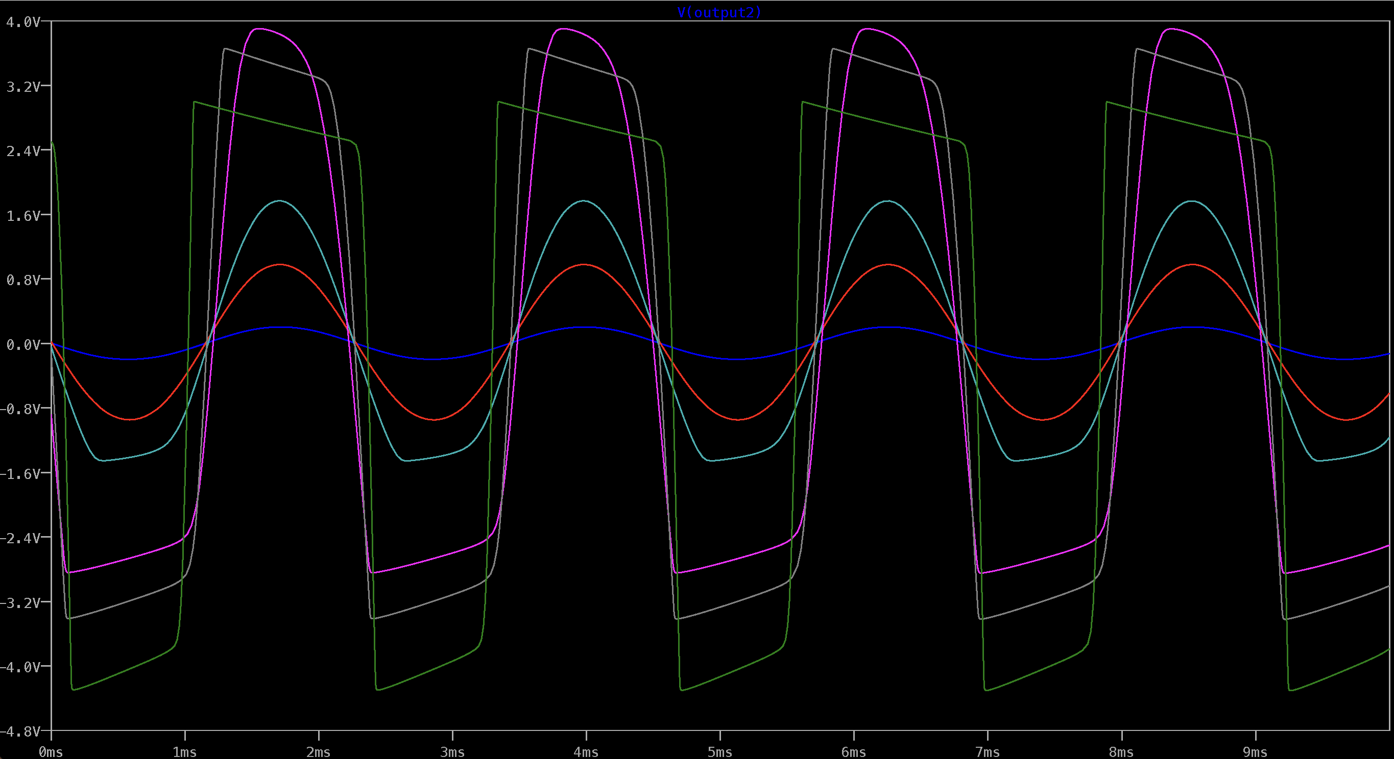
With a 5n / 100n cap and a 100k filter pot, the response on the base of the transistor looks like this.  The output looks about the same with the 100n and 100k pot.  A 47n cap looks pretty similar as well.

COLORSOUND TREBLE BOOSTER - STEVE WILLIAMS - FREQ RESPONSE

Being a silicon boost, they tend to be a cleaner wave than a germanium boost, although this does look to get some dirt as more bass is introduced.  It is just a simulation, so real-life results may differ - and honestly, you never want to hear a silicon treble boost that is not overdriving an amp - horrid...  

COLORSOUND TREBLE BOOSTER - STEVE WILLIAMS - WAVE


Friday, August 8, 2025

COLORSOUND: 1971 Overdriver

The Colorsound Overdriver / Power Boost family went through a few different versions over the years. This layout is for the classic 1971 9V Overdriver version – essentially the 9V successor to the earlier 18V Power Boost, with the same basic three–transistor topology but set up for a standard single-supply pedalboard. It makes a huge, dynamic boost that can run from almost clean to a thick, fuzzy overdrive, with a very effective bass and treble control.

I went with the 1971 9V spec simply because 9V is more convenient, and I had one of the larger Gapco enclosures that suited the longer 0.15" vero format.  This layout also includes a post-gain volume control (master volume).  Original units did not have this, but given how loud the circuit is, most people prefer to keep the master.  If you really want to be vintage-correct you can omit it and wire the output straight from the gain pot.

There is a lot of excellent historical information on the Power Boost / Overdriver on Kit Rae’s site, including a clear explanation of the differences between the 18V Power Boost and the 9V Overdriver, and notes on various reissues.


COLORSOUND 1971 OVERDRIVER – 0.15" VERO LAYOUT


Layout notes: this is a 0.15" stripboard layout sized for a larger vintage-style enclosure. Check transistor pinouts before soldering – the original BC109 devices can be swapped for common modern NPN types if you re-orient the legs correctly. The added volume control is a true output master; if you omit it, take the output directly from the gain pot lug as marked.


COLORSOUND 1971 OVERDRIVER SCHEMATIC


COLORSOUND 1971 OVERDRIVER VIDEO DEMO

Here’s a short demo of this layout in use, showing the range from clean boost through to full overdrive.

Friday, July 11, 2025

D*A*M: Supa Rooster

Since I'm doing boosters at the moment - the D*A*M Supa Rooster.   

I'd suggest placing a 1m resistor on the input and output if you get switch pop - a lot of people do this all the time for their rangemaster type circuits.  If you want it to look true to the original, use 1/4w metal film resistors and sneak them under the board.

D*A*M Supa Rooster vero layout
Pretty much the same layout as the D*A*M pedal, can't see the value on a few components, but safe to say, that anything in the normal area of a rangemaster will be just fine.  I'm talking pot values and the smaller input capacitor in particular.  


Sunday, July 6, 2025

Germanium Variable Booster

Nothing groundbreaking today—just a variable-gain germanium booster I through together this afternoon, heavily inspired by the D*A*M Red Rooster.

I built mine on a slightly different layout, but if I do another one I’ll use this version; it’s cleaner and a bit easier to wire.  And if you like the idea of incorporating a trim pot instead of the 3k9 resistor, I'm sure you can work it out.

Thanks to the “range” pot, the top-end never gets as thin as a typical treble booster: a little signal always sneaks across the pot into the 1µF cap.  That gives you a smooth sweep from bass-trimmed sparkle to a rich, full-bodied soft fuzz—and it sounds sweet at every stop along the way.


Gernamium Variable Booster

The enclosure was a gift and came pre-drilled, which is why the jack holes sit so high up the side—strange and somewhat inconvenient placement, but it does the job.


I hid the 1m resistors under the board to save a bit of space, and I didn't have the same type as the 470k and 68k.  The 1m on the input and output almost eliminate switch pop, which tends to happen on rangemaster style circuits.


Monday, January 6, 2025

R2R ELECTRIC: Germanium Pre-amp

It's no secret as to what the R2R Electric germanium preamp is based upon, which is an old and very rare Hofner preamp.  The Hofner is a full-range germanium booster, which was once used as a way to plug guitars into old console radios way back in the day.

As this is a simple Rangemaster style circuit, any layout used for a Rangemaster could be used instead of the one below.  

R2R ELECTRIC GERMANIUM PREAMP LAYOUT

R2R spends a bit of time testing every component used, to get the sound that they're chasing. Since not all components are created equal, it’s worth dedicating time to testing and selecting components to ensure you get the most out of this simple circuit.

One notable choice is the AC107, which R2R recommends as a low-noise, higher-quality alternative to the OC44 or OC71 commonly used in Rangemasters. This decision is practical: while OC44s are highly sought after due to their use in Rangemasters, they’ve become increasingly expensive and are often prone to noise issues.

Side note:  An excellent podcast featuring Chris from R2R can be found here on the Fretboard Journal.   Chris talks about his journey and process. 


R2R ELECTRIC GERMANIUM PREAMP LAYOUT

And thanks to the person who very kindly helped out by sharing some photos of their pedal, confirming that the boost pot is wired the same way as a Rangemaster. 

I built it on tag strip, using the same layout - works just fine.  If you do the same, careful with the size of the caps either end as it’s a very snug fit in a 1590B


Boost / Volume pot:  R2R implemented the volume/boost control in the same way as the Rangemaster. The stock Hofner circuit uses a 10k resistor to the collector and has no volume control - R2R replaced the 10k resistor with a 15k pot. If a 15k pot is hard to source (as it's an uncommon value), try a 25k pot with a 39k resistor across pin 1 & 3 - this will drop it down to 15k.  Any resistor between 33k - 50k will get you close enough to 15k.  Pots are rarely bang on spec, so not something to stress about.   You could also experiment with a 10k pot to see how it goes.

Input resistor:  There's no need to worry about using the exact value for the input resistor. The stock Höfner schematic specifies 37k, which is an unusual value. R2R opted for 36k. As long as your choice is close, it should work fine.

It’s worth noting that the input resistor forms a voltage divider with the 10k resistor connected from the transistor base to ground. Together, these resistors reduce the input signal by about 80% before it’s amplified by the transistor.

Emitter resistor: The stock Hofner circuit uses a 1k5 emitter resistor, but there's room for variation, which can be tuned to match your chosen transistor. The R2R layout uses a 3k9 resistor, like the Rangemaster. Smaller values are more likely to produce some dirt, while larger values will result in a cleaner sound. This is a great spot to use a trimmer pot if you want adjustable control.

Capacitors and Bias Resistors:  The capacitor values and the 100k/10k bias resistors remain consistent across designs. However, there's flexibility with the capacitor values:

  • The input capacitor can be reduced significantly without noticeable changes in response. For instance, 1u is nearly indistinguishable from 4u7.
  • The 100u emitter bypass capacitor can be reduced to 47u with minimal impact.
  • Similarly, reducing the output capacitor slightly will have negligible effects on the sound.

Of course, collectively changing a lot of component values at once will increase differences, but ultimately, it is just a fairly generic single transistor booster in therms of the circuit.

Drop down resistors: R2R included 1M input and output drop-down resistors wired to the stomp switch, which you can see in the photos below. These are not present in the Höfner circuit but are a common addition to prevent switch pops. Including them is recommended.

Board:  I’ve not listed the size of the board or any other info on the point-to-point layout - I’m sure you can work that out yourself. 


Images below from a prototype - the 1k5 resistor may not have made it into production models.


Thursday, April 25, 2024

FENDER MDX Circuit / AION FX Elite boost / preamp

There's a few variations of this circuit, so I'd recommend reading through the Aion FX build docs or maybe just skip the vero all together and buy the board from them.

The build docs also include LTspice simulations of the frequency response, so that saves me a bit of time plotting them out.

I've labelled a few of the components where variations occur, but not all.  You should be able to work out the ones that I haven't labelled easily enough.

FENDER MDX CIRCUIT / AION FX ELITE BOOST / PREAMP VERO LAYOUT

FENDER MDX CIRCUIT / AION FX ELITE BOOST / PREAMP VERO LAYOUT


Vague explainer / demo here


Monday, October 2, 2023

RANGEMASTER BOOSTER

Just a Rangemaster with a rotary switch for selecting input capacitors - it uses some odd parts, as this is what was available in my local electronics store - the 5 lug tag strip in particular, a regular Rangemaster is on 6.  It's also a slightly odd rotary, but it was all that was left in the draw.

RANGEMASTER BASED GERMANIUM BOOSTER - VARIABLE FREQUENCY

RANGEMASTER BASED GERMANIUM BOOSTER - VARIABLE FREQUENCY

You may also want to add a small cap ( 470p / 1n) across the input to the base of the transistor, so there’s always a capacitor in the circuit - this reduces switch noise on the rotary.  I don’t think it’s massively important,  as I’m a set and forget kind of guy.  

Do check the numbering on the rotary, as the ones that Ive been using are in reverse, compared to the layout.  i.e.  start with small cap values on the left.


RANGEMASTER BASED GERMANIUM BOOSTER - VARIABLE FREQUENCY - BUILD PHOTO


Expect some hiss - this circuit is infamous for it, but it does sound good so most people overlook this.  Having a rotary with a few capacitor options is so much better than the stock Rangemaster treble booster - the additional range of sounds is well worth it.  The full range boost can get a little fuzzy, which is something that I was not expecting. 


While it was pretty quick to put the Rangemaster board together, it wasn't fast to wire up the rest.  There was a bit of fiddling with lining up the capacitors on the rotary, and the general position of the tag strip didn't help matters.   

Same again, but this time with a pot to help set the gain, instead of a 3.9k resistor.  This is hand to dial in (or out) the grit that can really make treble boosters shine. 


Tuesday, July 25, 2023

HOFNER: Germanium Pre-amp

I only came across the Hofner Preamp quite recently, despite seeing some other builders making point-to-point style germanium preamps based on this circuit - the prime example being the R2R Electric preamp.

There's a good write up here, but in summary: Back in the day before guitar amps were affordable, and TV was a thing, pretty much everyone had a big valve radio in the house.  Many had an input for turntables, but most people didn't have a turntable as they were expensive.  So Hofner made a preamp to allow early electric guitars to be plugged into a valve radio, via this additional and often unused input.   

The preamp boosts signal and helped fix the massive impedance difference, turning the family radio into a primitive guitar amp.   

Worth noting that old record players had a much higher output than the current ones, hence the need for a boost.  The output was so high, that when you look at old schematics for valve PA systems, the P.U. input skips the first 12AX7 gain stage, and goes straight to a mixer, so guitars really needed an extra boost to make it work.


HOFNER PREAMP SCHEMATIC

Hofner preamp schematic

It kicks out a good 20dB of boost and has a relatively flat response
  

I'd be very surprised if the boost is as clean as it looks on LTspice - I'll have to breadboard this and check it out on the scope.  I'm sure there would be some dirt.


MODS

I guess the first and most obvious is adding a volume pot.  A 220n output cap is pretty healthy, so a standard A100K volume pot will work just fine.   Note the R2R electric method, which is similar to a rangemaster.  This is probably a better way to do it. 

Reducing R1 increases the input level, as it normally forms a voltage divider with R2.  Things will get a little fuzzy and overdriven.

C1 can be reduced to treble booster territory. 

C4 can be reduced for a bit of low-end roll-off.


TAGBOARD & VERO LAYOUTS

The original was constructed in a very similar fashion to the Rangemaster - a simple point-to-point circuit in a box.  

HOFNER PREAMP TAGBOARD LAYOUT


HOFNER PREAMP TAGBOARD LAYOUT


Saturday, February 4, 2023

PETER SINGFIELD: Treble Booster (a quieter one)

I came across this while browsing one of the usual forums recently and thought it looked like an interesting Rangemaster variant.   Silicon or germanium transistor, variable boost, quiet, standard power supply...  seems to have a lot going for it as far as treble boosters go.   

Here's the thread on DIY Stompboxes (Peter is FSFX) and there's this documentation detailing the noise reduction.

Naturally the input caps can be tuned to taste, and the range pot can be completely removed or replaced by a switch if that's your preference.


PETER SINGFIELD - A QUIETER TREBLE BOOSTER - VERO LAYOUT

PETER SINGFIELD - A QUIETER TREBLE BOOSTER - GUITAR EFFECT VERO LAYOUT RANGEMASTER


Sunday, January 8, 2023

AIWA: TP-1011 Reel to Reel Preamp

The AIWA TP-1011 is the reel-to-reel tape preamp Richie Blackmore from Deep Purple used to drive his Marshall.  I'm not a huge Deep Purple fan, but I do like the sound of some of these old reel-to-reel preamps.  This layout is for the stock circuit running at 18v.  If I ever get around to breadboarding the mods I tried in LTspice, I'll post another layout.   

Here's the discussion on FSB, including a verified layout with a trimmer to control the first gain stage.


AIWA TP-1011 REEL TO REEL PREAMP - VERO LAYOUT

AIWA TP-1011 REEL TO REEL PREAMP - VERO LAYOUT


Build notes (comments below from ConvergentSound);
  • The stock version sounds awful at 9v
  • Replacing the 56k with a pot is necessary to control gain

SCHEMATIC AND POTENTIAL MODS

Reduce down from 18v to 9v.  18v had mountains of output level on tap - I can see how stories of Blackmore cooking amps could be true.

  • Reduce coupling cap size to roll off some low frequencies   
  • Very flat response with the stock circuit
  • Aiming for clean boost all the way to fuzz
  • Try NPN germanium for Q3   
  • Trimmer to control gain of the first stage (as per FSB thread)


AIWA: TP-1011 reel to reel preamp schematic with mods.  For guitar effect pedal builds


NOTE:  images below are from the modded circuit running at 9 volts.   The original will distort quite quickly, which seems to be normal.  Basically to the point of fuzz.  

AIWA TP-1011 REEL TO REEL PREAMP - Mods on LTspice

AIWA TP-1011 REEL TO REEL PREAMP - Mods on LTspice

Saturday, October 22, 2022

ELECTRA: Modular Powered Circuits - MPC11 Frognose Amp

Onto the Frognose - weird name right?  It's based on the LM386 IC, which is an audio amplifier capable of driving a small 8-ohm speaker.

In the configuration below, it's capable of 20x gain, so it's a pretty decent booster.

If you aren't familiar with the LM386, two of them are used in the Earthquaker Devices Acapulco Gold, and one is used in the D*A*M Sonic Titan with a JFET boost in front.  So if you put the Electra Power Overdrive in front of this, and added an extra cap to the LM386 you would have something resembling the Sonic Titan, or my version of this, the Kool Thing Distortion.  Not bad....  


FROGNOSE MPC11 - SCHEMATIC

Schematic was drawn by Steve - thanks Steve, hope you don't mind me posting it here.   

FROGNOSE MPC11 - GUITAR EFFECT


As you can see, the Frognose is an almost part-for-part copy of the implementation provided by the manufacturer of the LM386.


VIDEO DEMO


Saturday, July 23, 2022

THORPY FX: Heavy Water

A nice booster from Thorpy, most likely Dan Coggins design.  The build notes from PedalPCB suggest germanium diodes across the opamp for a dirty boost.

Schematic can be found here

THORPY HEAVY WATER BOOSTER - VERO LAYOUT

THORPY HEAVY WATER BOOSTER VERO LAYOUT FOR GUITAR PEDAL BUILDERS


This puts out a lot of level, and the low cut can put it in treble boost territory on extreme settings without any trouble at all, otherwise generally handy to cut a bit of bass to tighten things up on the lower end. 

I haven’t included a trace of the wave, as it basically looks like a big sine wave - a bit of change with the bass cut, but nothing worth looking at.  


Thorpe heavy water freq response


THORPY HEAVY WATER BOOSTER - VIDEO DEMO


Thursday, May 12, 2022

JOHN HORNBY SKEWES: Selectatone TB2 Treble and Bass Booster, Tag Board Layout

While on the JHS thing, I noticed this booster and thought it looked interesting.  The output switches between filters to allow for treble and bass boost, unlike most other boosters where it all happens at the input.

Very few seem to be around, as I could only find one photo of the internals and one video demo.  The schematic still has a couple of assumed (but working) values, which are explained below and marked on the layout.

There's a bit of off-board wiring, which is how the original was built - and no volume control.  

JOHN HORNBY SKEWES SELECTATONE TB2 - TAG BOARD LAYOUT

JOHN HORNBY SKEWES SELECTATONE TB2 - TAG BAORD LAYOUT


Image credit: Effects Database https://www.effectsdatabase.com/model/jhs/selectatone#


LTSPICE RESULTS

Both with 100n for the input cap (C1), and the cap linking the treble bass switch (C2).


Changes to the 100n caps (C1, C2) mentioned above have almost no impact on the frequency response of the treble boost (right down to 22n), so tweaking these caps is more around tweaking the bass boost to your liking, and there will be some changes to how it distorts as well.


I split the circuit into two for bass and treble boost, as switches are painful in LTspice - simple SPDT / DPDT switches don't exist.  

For nerdy folks familiar with spice, here's what I was doing (schematic below).   

Short story for lesser nerds, a smaller C5 cap in the bass boost section raises the boost level and shifts it towards the mid-range.  C2 tunes how much low-end roll-off there is.  i.e. you might want a low-mid boost without the flabbiness of too much low-frequency content.

C1 impacts the response, affecting how the transistor distorts, so it's worth trying a 47n in there and a 100n.

Basically, breadboard it and play with C1, C2, and C5. 


Treble boost vs Bass Boost


Input cap variations effect on the Treble Boost output


VIDEO DEMO


OC71 vs 1T308 TRANSISTORS

Spot the difference?  Someone had a question in the comments, so I thought I'd quickly breadboard it for a look - note that this is from the 100n cap on the output, not after the high pass filter.

So turns out they look almost identical, and voltages also measured about the same.   


Wednesday, May 4, 2022

ANALOG MAN: Beano Boost

The Analog Man Beano Boost takes the classic Rangemaster treble booster and adds a very useful function — a switched input capacitor that widens the tonal range beyond the original’s treble boost.

Because it’s a single-transistor germanium circuit, the choice of transistor does shape the tone and clipping character, especially at higher gain settings.  That said, you don’t need to hunt down an expensive vintage OC44 to get great results.  Many germanium transistors will work really well in this circuit — just be mindful of noise, as a bit of hiss is common with older germanium devices.

Quite a bit of info here on Analog Man's website 


ANALOG MAN BEANO BOOST - TAG BOARD LAYOUTS

ANALOG MAN BEANO BOOST - TAG BOARD LAYOUTS


Same again, but with a pot to control the gain - with the 5k pot at around 50% the series resistance is about 3.5k depending on component tolerances.  I think this is close enough to the stock 3.9k - you could use something a bit larger than 1k to get it closer, but it really doesn't make a massive difference.

This is handy for finding the sweet spot for just the right amount of grit in the boost.  Another useful option is to replace the 68k resistor with a pot (100k as an example).  One of the Steve Williams boosters has this addition - minor downside, the pot has DC on it, so it will sound scratchy / crackly.


ORIGINAL BEANO BOOST LAYOUT

This is one of the layouts used by Analog Man.  Note that I've done it in two layers, as it's hard to show parts directly underneath each other in this format.  


IMPORTANT: the mounting points on the strip must be isolated from the enclosure 

VIDEO DEMO