Showing posts with label UTILITY. Show all posts

Sunday, February 2, 2025

UTILITY: Speaker Cab Impedance / Speaker Switch

When I set out to build a proper test cabinet for amp building, I came across a great switch wiring setup that perfectly suited my needs. With the parts I had on hand, I was able to put together a versatile cab without risking damage to my favourite speaker cabs.  There are of course commercial products that achieve the same thing, and sometimes more.  But this is a DIY blog right.  

Why a test cab?  I already own several cabinets that I really like, however, I was a bit concerned about accidentally destroying a vintage speaker.  A dedicated test cab allows me to safely experiment with different speaker loads without worrying.

What You’ll Need

  • A twin-speaker cabinet with 8-ohm speakers
  • A 3-pole, 4-position rotary switch (Make sure it's a sturdy one, ideally rated at a couple of amps)

There are four switch positions, covering the most common loads:

  • The first two switch positions isolate the individual speakers, providing an 8 ohm load.  Handy if you have two different speakers in a cab that you want to isolate.
  • Position three is both speakers in series, providing a 4 ohm load
  • Position four is both speakers in parallel, proving a 16 ohm load
I kind of rushed into throwing this together, and now I want this to rework this to put it in sequential order...  4, 8, 8, 16.    


A Word of Caution

WARNING: If you wire this incorrectly, you could fry your amp’s output transformer - a costly mistake.  Always triple-check your wiring with a multimeter before plugging in your amp.  If you're unsure or don’t have the tools to verify your work, do not attempt this.

4-WAY SPEAKER / IMPEDANCE SELECTOR

Speaker Cab Impedance / Speaker Switch


The wiring diagram I used was posted by YellowBoots on the Tele forum


TEST CAB

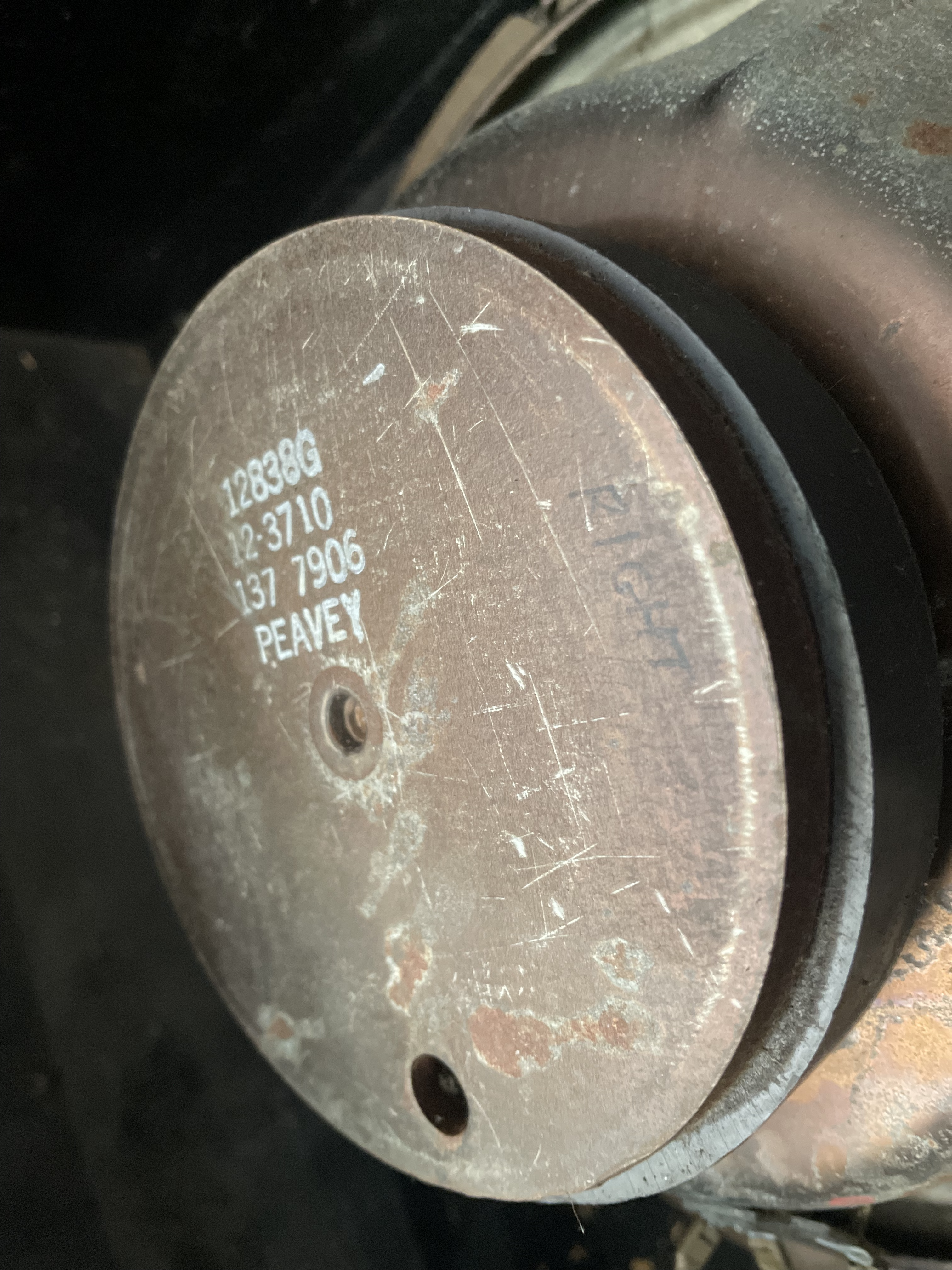
The cabinet I’m using is a late '70s Peavey Deuce combo, minus the amp.  It houses two 12-inch CTS speakers, which I think are rated at 50W to 75W each.

It's quite a well built twin 12 combo cab, proper ply etc instead of the awful stuff they use these days in most amps.  I have it sitting on wheels, so it's easy to drag around the workshop.


Yes, I will eventually label it properly, but for now, this will do.  


I gave the new test cab a run with this little AWA PA 774 amplifier.  I modded it to have a Fender style preamp with bass and treble controls, cause I only had three knobs to work with.  It's a cool little amp and sounded great through the cab.  As I'm not a fan of the look of the old peavy cabs, I pulled the aluminium strip and logo off the front. 


Wednesday, January 8, 2025

UTILITY: Test Box

When you're diving into breadboarding or building circuits, one thing becomes clear—you need a test box.  It can be used with a breadboard or a completed circuit, before you spend time boxing it up in a finished enclosure.

Testing using an enclosure that is known to work eliminates one area of trouble shooting, which often stumps new builders - and that is of course off-board wiring.  If you don't have a firm understanding of off-board wiring, you really need to spend some time on this, as it's crucial to building a working pedal.  

It's also handy that the test box can plug into a regular pedal power supply, battery or bench top power supply - basically treat it like a regular pedal, with a few extra benefits.   Before I had a full workshop set-up, my test box was mounted on a piece of plywood with a breadboard next to it, so I could carry it from the dinning room table to my amp to test (it didn't take long for the wife to suggest an alternative workspace).

I’m still using the very first one I ever built, which looks a right mess, but it works. 


TEST BOX WIRING DIAGRAM

It's fairly simple - it's just normal off-board wiring.  Use whatever switch wiring you prefer; the wiring below is probably the most common and easiest to understand, which is why I used it in the diagram.  It's not what I use in my pedals these days, but is it what's in my test box.  I prefer a wiring scheme with the circuit input grounded when bypassed.


guitar effect test box wiring diagram


Here's how to build your own:

REPURPOSE
Find a failed project or an old pedal casing you no longer need.  Remove the original circuit, but leave the rest of the components intact.  This gives you a good starting point.

MAKE SURE IT WORKS
Before anything else, test the existing stomp switch and make sure it works.  Reliability is key for your test box, so it's important to verify this first.

TERMINALS
On the top of the enclosure, mount the test sockets.  Personally I like the banana binding sockets as they're really designed for this kind of thing.  You can plug into the top, and/or secure wires with the screw down connection at the bottom.  

Some people use speaker terminal connections - while they work, you have less options for connections.

You will need the following connections:

  • Circuit input
  • Circuit output
  • 9V power
  • Ground
SWITCH 
Solder the input and output terminals to the corresponding contacts on the switch (where the old circuit was attached).   Stomp switches are easy to damage with a hot iron, when recycling an old enclosure, do as little as possible and do it fast.

JACKS 
I moved the input and output jacks to the top of the enclosure, as I found it easier to work with on a bench.  

POWER & GROUND
Solder the 9V and ground connections from the old, removed circuit to the newly mounted terminals.

DC / BATTERY CONNECTION
There's no battery connection, as I prefer to test circuits using a generic pedal power supply.  Why?  The cheap power supply should highlight any issues you have with circuit noise - if you plan on selling the pedal, it's good to know that it sounds fine on a terrible power supply.   

I do attach a battery to the terminals or breadboard at times to test vintage style circuits, as I don't always include the option for a DC connection on the vintage style pedals that I make.  I think a battery is the best possible supply of DC power, as it's isolated and ripple free.  That being said, I've never had an issue with my Voodoo Labs power supply using vintage style positive ground circuits with next to no power filtering or protection.    


Saturday, January 4, 2025

BREADBOARD: How To

Breadboards are one of the most effective learning tools when it comes to electronics.  Not only are they great for prototyping and testing circuits, but they also offer a hands-on way to fine-tune and troubleshoot designs—perfect for testing guitar pedals.

In this post, I’ll walk you through how I use a breadboard.  While this approach may not be for everyone, it’s a method that’s worked well for me, and it could help you get more comfortable with circuit building. 


Testing transistors for the Colorsound hybrid fuzz box.  This cheap breadboard doesn't have the power rails connected as per normal - I had to jumper them.

HOW TO USE A BREADBOARD (For Guitar Pedals & Electronics Beginners)

So, where to begin?  You will need:

  • a breadboard
  • power supply - bench top, battery or pedal power supply will do
  • components to play with
  • jumpers, which can be solid core wire, or you may have a bunch supplied with the breadboard
  • input / output jacks, ideally with an on/off switch, or better yet a test box
You also need to be able to read a schematic and have some basic understanding of how the circuit works.

PLANNING TO BREADBOARD A PEDAL

I don’t typically pre-plan my breadboard layouts.  I’ll take a quick look at the schematic and then dive right in.  Early on, I tried using DIYLC (software for creating vero layouts) to map out my builds, but I found that breadboarding is a hands-on, three-dimensional process.  Once I started placing components on the board, my plans usually went out the window—so I’ve learned to just dive in and adjust as needed.

SO HOW DO THEY WORK?

Breadboards are relatively simple. They consist of rows and columns of holes that are electrically connected in a grid pattern. Along the edges of the board, there are vertical power rails—one for positive voltage and one for ground. You can buy fancier breadboards with additional features, but they all work in roughly the same way: you place your components and make connections using jumpers.

COMPONENT PLACEMENT ON THE BREADBOARD

When I build a circuit on a breadboard, I aim for a logical, linear layout.  I don’t try to make the circuit as compact as possible.  Instead, I leave a little bit of space between components to allow for easy adjustments and troubleshooting.  Generally if you're breadboarding, you will be swapping components in and out and this means leaving room for clumsy fingers.

For simple circuits, the main goal is making sure everything fits on the board and is properly connected. Once you get into more complex builds, you might need to think about space a bit more, but for testing pedals, spaciousness is often your friend.


For some circuits, I'll build most of it on vero, and then test some components on the breadboard.  There might be a particular section that I want to play with and test, without having to build the entire circuit on the breadboard.  I often use little clamps for this.

TESTING THE CIRCUIT

Usually I feed the circuit a sine wave from my signal generator and test that it's working as expected on one of my scopes.  You could easily use an audio probe to do this as well.

For larger or more complicated circuits, I test as I build, making sure that each stage works.

After it's confirmed to behave as expected, I usually plug in a guitar and run it to my amplifier, as real world testing is the always the best.  Just need to be a little cautious here - I have an amp that I'm not attached to for this purpose.  I've never killed an amp in testing, but there's always a chance right?   There is often a bit of popping and unsettling noises when touching parts on the board - just be aware of this.  

When testing, I usually have a selection of parts to swap in and out to see how they effect the sound - in some cases I'll use a pot instead of a fixed resistor to sweep values.  When I find a setting that I like, I'll take the pot out of the circuit to measure the value and replace it with the nearest value fixed resistor.

For transistors and caps, it's just a case of swap them and see what happens.  

I usually have a few pots sitting in the parts draw with solid core wires soldered on for breadboarding.  It's handy to be able to swap a few around to see what works better for you in the circuit.

TROUBLESHOOTING

OK - you've put all your parts on the breadboard and it looks fine, but it doesn't work.  What next?  Same as testing a regular circuit, check your voltages and probe the circuit to see where you went wrong.  

It's often a component leg in the wrong hole, or a possibly a poor connection somewhere.  Poor connections can be a thing with cheap or dusty boards, quite often on the power or ground rails.  I normally tap and wobble parts to see if they make noises, maybe reseat transistors.  In short, if it doesn't feel secure, it probably isn't a good connection.  Although this could also be a sign that I need to spend more on my breadboards instead of getting cheap ones for a few dollars from China...

PRE-BUILD TESTING

In some cases I breadboard the entire circuit that I plan on making on a breadboard first, using the components that will be used in the final build.  This is usually only for circuits that I know will be tricky to tune.  Example: a MKI Tone Bender.   In some cases I’ll just use the breadboard to test the transistors and not worry about the rest of the circuit.  

OPTIONAL:  COMPONENT LABELS

If you're like me and don't have the best eyesight, small masking tape labels on the legs of components is sometimes helpful.  Especially when you start pulling out small metal film resistors and leaving them all over the bench.  

I can read 4 band, 1w carbon films easy enough, 1/4w metal film is a tad tricky for me.  Sometimes I avoid using 1/4w metal film for this reason.  Same can be said for some caps - greenies are sometimes hard to read.  I sometimes write the value on with a marking pen.


Wednesday, June 29, 2022

JOE DAVISSON: Diode Compression Opamp

Given that I've been playing around with a few circuits using this as a replacement for the opamp, I thought I should make a little vero layout, which can be dropped into an existing circuit to test it.

If you are unfamiliar with this, it's a simplified discrete opamp - basically, build it, and place the appropriate leads into the matching locations in the socket for any standard opamp (TL071 as an example).  Of course, if it's a dual, you will need two...

The schematic and more information can be found via this link

But why?  There are heaps of perfectly good opamps out there.  That's a very good point - it sounds different in most cases, to my ears a little smoother; perhaps something to do with the lower gain?  Apart from that, it's just another fun thing to play with.


JOE DAVISSON DIODE COMPRESSION OPAMP - VERO LAYOUT

JOE DAVISSON DIODE COMPRESSION OPAMP - VERO LAYOUT


Saturday, February 12, 2022

ABY Amp Switch Box

I recently tried building an ABY box with isolating transformers on the outputs, and I just could not get it to work (well, everything worked, apart from the constant buzzing that I could not get rid of, which was incredibly frustrating). 

I then pulled out most of the components, just leaving the switching and LED indicators, which worked without any buzzing; however, I did want a phase switch, which brings me to this.  

It's a simple opamp buffer running on a dual rail supply for ample headroom, and it also has an inverter to flip the phase of channel B if required, or maybe you just like the sound of out-of-phase amps.   

Any dual opamp can be used, and if you only have 7660 instead of 1054 for power inversion, just remove the cut between pins 1 & 8.   If you feel uncomfortable about the lack of a capacitor on the buffer's input, there's room to add one - I'm sure you can see where and how.

If you have two amps and no switcher, you're really missing out - buy or build one.


A/B/Y AMP SWITCH BOX - VERO LAYOUT

ABY AMP SWITCH BOX - VERO LAYOUT


This is for switching inputs to amps only - if you try switching speakers/cabs, bad things will happen....  it also does not work in reverse, as a passive switch does.

Monday, January 18, 2021

SMALL BEAR: Germanium Transistor Test Method

Given I listed the RG Keen method, I thought I should add the Small Bear method as well.  It's a simpler test that some people prefer, and it's generally considered not as accurate as the RG Keen method but close enough for most purposes.

NOTE:

  • Be prepared to see the voltage fluctuate a lot while the transistor stabilises.  Don’t wait too long though, as you will be there forever - it may never stop!  
  • Handle the transistor as little as possible with your fingers, as the heat will transfer
  • Different environments will provide different results - this is very temperature dependant 
  • With all methods, the test results will vary, depending on the method used.  Why?  Without attempting to explain the math that I don't fully understand, hFE varies with the current applied to the base.  Different test methods and test equipment apply different currents, so results will differ.
Small Bear germanium transistor test method


Sunday, January 17, 2021

IC Test Clips, Vero Clamps

I discovered this nifty little hack today, maybe you already know about it, but it's new to me.

After improving my germanium transistor test kit yesterday, I thought I should also upgrade some dodgy leads I’ve been using with my breadboard.  

I sometimes start building on vero, then solder wires on temporarily to test different component values on the breadboard.  While it works, it was messy and time-consuming, and it turns out there's a much easier way to do this (at least for edge connections).   

I bought some IC test clips and wired them up for the breadboard.   As it turns out, the IC clips aren’t just good for ICs - they also grab the edge of vero board quite tightly, making them perfect for testing without resorting to tacking on wire.

At nearly 60mm long, these are a decent size clip and are quite sturdy.  The smaller 30mm version still works; they are just less stable and feel less solid.


The stock clip doesn’t fit through veroboard holes, but I did manage to bend one of the smaller clips slightly, so it will go through holes and clamp anywhere on the board.  Very handy indeed.


The stock clip is on the left and modified on the right.


Saturday, January 16, 2021

TRANSISTORS: RG Keen, Germanium Transistor Test Method

If you haven't heard of this before (which seems unlikely), here's the original RG Keen article, which explains how it works.  I use a spreadsheet set up with the calculations ready to go for testing; there's also an online calculator here.


NOTE:
  • Be prepared to see the voltage fluctuate a lot while the transistor stabilises.  Don’t wait too long though, as you will be there forever - it may never stop!  
  • Handle the transistor as little as possible with your fingers, as the heat will transfer
  • Different environments will provide different results - this is very temperature dependant.
  • With all methods, the test results will vary, depending on the method used.  Why?  Without attempting to explain the math that I don't fully understand, hFE varies with the current applied to the base.  Different methods apply different currents, so results will differ.

RG KEEN METHOD FOR TESTING GERMANIUM TRANSISTORS

RG KEEN germanium transistor test


LEAKAGE TABLE FOR RG KEEN METHOD

If you just want to know how leaky the transistor you’re testing is, here's a quick guide (numbers have been rounded for ease of use).  This only applies to the RG Keen method.

VDC        LEAKAGE - uA
0.1           40
0.25         100
0.5           200
0.75         300
1.00         400
1.25         500
1.50         600
1.75         700
2.00         800


TESTER BUILD

I recently purchased a small multi-function tester, and while it's great for so many different measurements, I wasn't completely happy with the leakage results on germanium transistors - maybe it's just not what I'm used to...   

I've been using a tester that I built using a layout from Guitar FX Layouts  and while it works, it's very small, and I found that the transistor socket got a bit loose over time.  It was just a bit fiddly for me.  

So today, I built something a bit more robust from some scrap 0.15" vero, I kind of worked it out as I made it, so the layout below is not an exact match.  

  • Pins to insert in a breadboard rather than use a socket
  • The switch is mounted through the board, and I used a trimmer for biasing the collector

It's not the best-looking thing I've ever made, but it feels solid, and it works as intended.  I wish I had more colour options for the wires and shrinkwrap to make it easier to identify the leads, but it's not the end of the world.   I might even get around to mounting it in an enclosure one day with a small breadboard attached.


This is a rough layout, not identical to the one I made, but you get the idea.  

NOTE:  
  • This is specifically laid out for PNP germanium transistors; if you want to measure NPN, reverse the polarity of power and the multi-meter
  • Components must be as close as possible to the values provided to provide the most accurate results (including voltage)

Sunday, July 26, 2020

POWER: MAX1044 Charge Pumps and Inverter


MAX1044 charge pumps and 9v inverter


Note:  Normal power ripple filtering can be added to these.  Probably better to add filtering after the IC rather than before (or both ends if you are really keen).  

Thursday, July 23, 2020

POWER UTILITY: Power Filter / Capacitance Multiplier, Point to Point and Vero Layouts

Power your fuzz / high gain circuits with noise problems from this.  Like most things, it's not a silver bullet for your problems, but it will probably help.

Here's a better technical explanation than I will ever manage.  There's a few variations of this circuit - google is your friend if you want to find out more.

TLDR:  It will reduce ripple on DC power supplies a lot.


DC POWER FILTER / CAPACITANCE MULTIPLIER - POINT TO POINT AND VERO LAYOUT