Showing posts with label AMP. Show all posts

Sunday, November 24, 2024

BELL & HOWELL: Model 601 Amplifier Conversion Project

When I started this project, I knew some people prefer to keep these amps stock. However, running something with electrolytic capacitors from 1948 seemed like a disaster waiting to happen. If one failed, it would be a nightmare to fix. In fact, if anything failed, the cramped design would make repairs extremely difficult. On top of that, quite a few resistors were wildly out of spec after 76 years, so leaving them as-is wasn’t an option.

That said, I completely understand the hesitation to modify one of these amps. The lack of space in the chassis makes them a real challenge to work on. Every step required careful planning and a lot of patience. This wasn’t a quick project by any means.

Below is the conversion path that I've taken.  Here's a link to my original post with photos etc

1949, BELL & HOWELL GAUMONT, MODEL 601 REBUILD

The Model 601 is often compared to the Filmosound 179 - essentially the British versus the American version.  While they look similar, there are schematic differences.

For the Tech Nerds:

This amp features:

  •  A 6J7 pentode preamp stage
  • A cathodyne phase inverter using a ECC35
  • A cathode-biased 6V6GT push-pull power stage (no grid stoppers or screen resistors)

The phase inverter and power stage are reminiscent of a Tweed amp, which makes sense given its vintage. However, the standout feature is the unique tone control—more on that later.


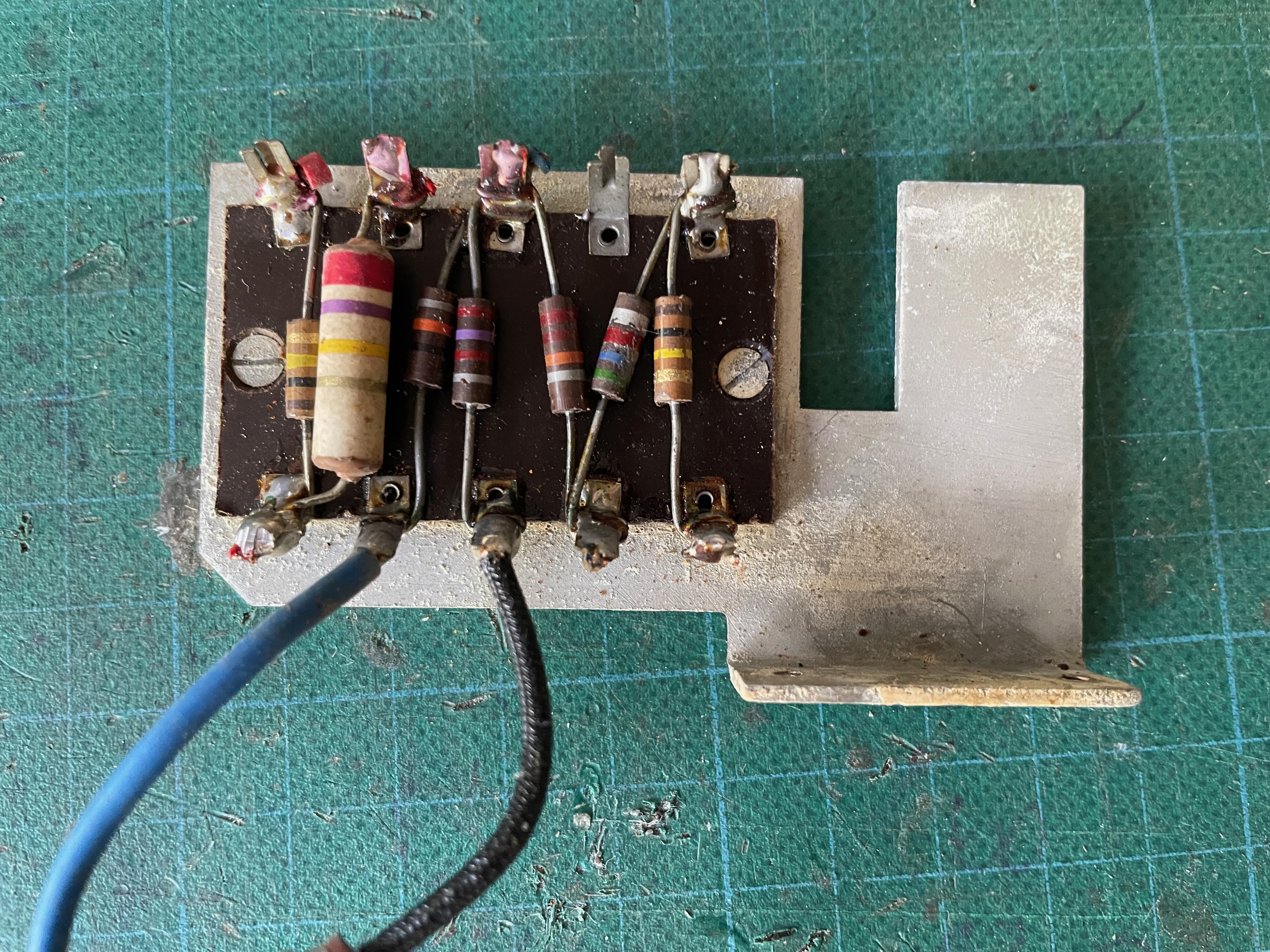
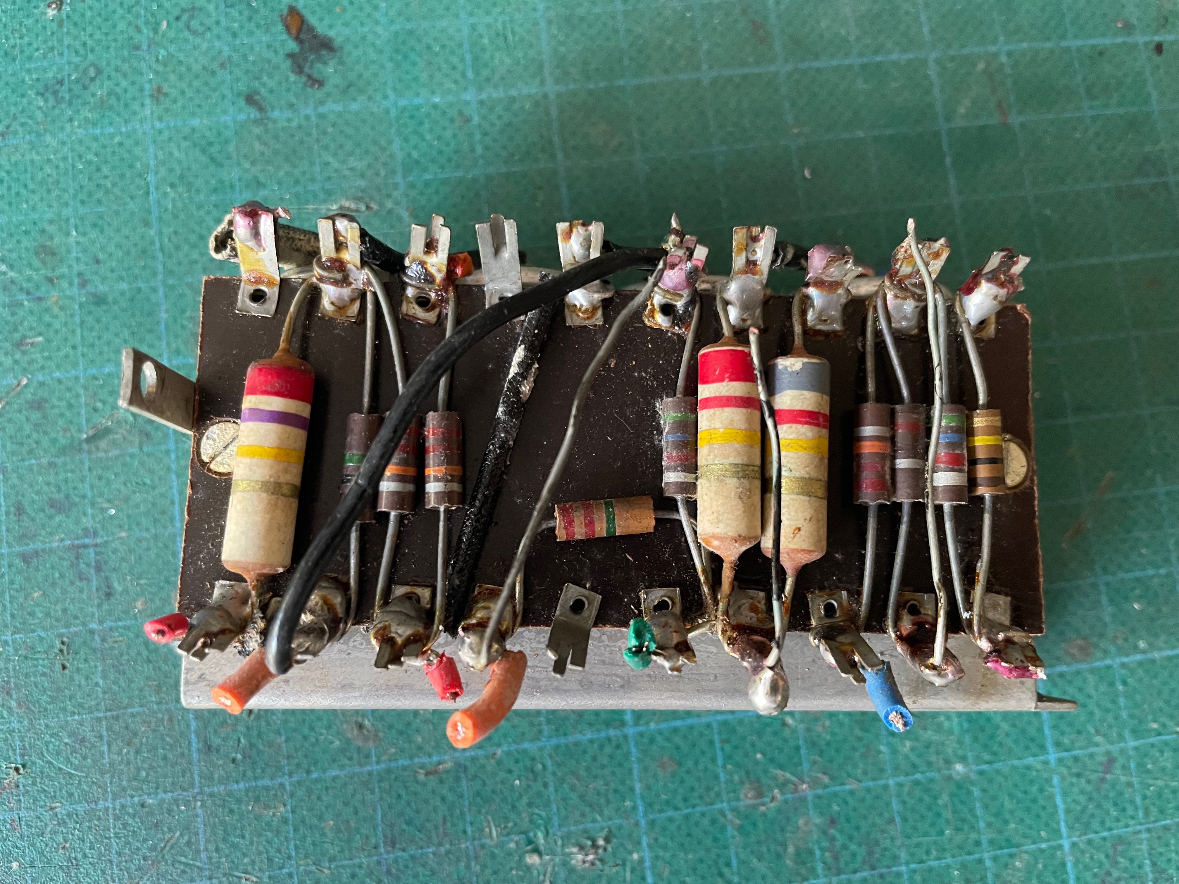
The next two images below are two sides of one board - in the image above, the board is jammed into the top left corner.  You can see the positive end of the caps poking out.  The negative ends were soldered directly to the aluminium frame that they're attached to.


Perhaps unsurprisingly, a lot of the resistors have drifted out of spec over the last 76 years.  Unfortunately many are too far out of spec to use.


STRIPPED BACK TO THE ESSENTIALS

Stripping the amp down was painstaking. With so many components crammed into tight spaces, it must have taken a meticulously planned assembly line process to build these back in the day. You’d definitely want to get it right the first time.

Here’s what it looked like stripped back to the essentials, with just a few components, transformer, and heater wiring left in place. (excuse the masking tape, that was my labelling system)

BELL & HOWELL GAUMONT, MODEL 601 CONVERSION

POWER SUPPLY

The first task was tackling the power supply - cause if that doesn't work...  . Here’s what I changed:

New Power Connector: I replaced the original four-pin Jones power connector with a standard IEC socket. This required some filing on the chassis but made the amp much more practical.

Modern Fuse Holder: The old fuse holder used an uncommon fuse size, and I wasn’t confident in the aging plastic. A modern replacement solved this issue.

Filter Capacitor Replacement: I swapped the original 16uF + 16uF capacitor for a new F&T 16uF + 16uF 500V cap. While I considered reforming the original cap, its size and age made me hesitant to leave it in the circuit.


OUTPUT JACK

I added a new output jack between the existing two-pin connectors for convenience, opting for the 16-ohm tap from the output transformer. The 8-ohm tap is insulated and tucked away.  Maybe I'll put them both on a switch one day.

bell and howell guitar amp conversion

REBUILDING THE CIRCUIT BOARDS

Many builders opt for point-to-point wiring after gutting these amps, but I chose to use tagboards with my own layout. In hindsight, this didn’t make things much easier—it was still a tight squeeze! The tagboard I used has smaller spacing than the original, allowing me to fit more components.

Component Choices:

  • I replaced the out-of-spec carbon composition resistors with 1W carbon film resistors.
  • The original Hunts coupling capacitors were still within spec, so I reused them where possible. For the rest, I opted for mustard caps to keep the vintage aesthetic.

The layout I used isn’t a replica of the original, as I didn’t trace the circuit in detail. My focus was on creating something functional and serviceable, not an exact restoration.


Below is the layout that I used for the boards - I have no idea how close they are to the original, as I didn't spend the time to trace the circuit - cause I'm not that crazy.

I've intentionally left some of the wiring off the layout to hopefully discourage anyone that isn't sure about what they're doing attempting this.  It's not easy, I went slow and it was still a little frustrating to work on.

I did relocate the bias resistor on the preamp cathode to the valve socket, as there was room, and this makes it easier to measure bias or change at a later date.  Same could be done for the cathode resistor shared by the two 6V6.

Bell & Howell 601 rebuild layout

Note the dire sounding safety warning on the layout - this should be taken seriously if you are opening up any amp to poke around in.  

bell and howell filosounmd amp conversion gut shot

TONAL TWEAKS?

A few people have messaged or asked on socials what have I done to the circuit, or what circuit did I use.  It's almost the stock circuit, as I wanted to do as little as possible to the amp.
  • Simplified the preamp by removing the feedback circuit - it's a straight 33k grid stop with a 1meg grid leak.  Pretty standard.
  • I added a very low-value bright cap on the volume pot - 68pf.  It just adds a little bit of air to the top end, without changing the character of the amp.  
  • Increased filter cap values, but not excessively so by modern standards.  4uf up to 10uf, 8uf up to 16uf etc. 

bell and howell 601

SPEAKING OF TONE

The tone control is one of the most intriguing aspects of this amp. It’s surprisingly complex for a film projector amplifier and operates quite differently from most guitar amps.

Here’s what’s happening (or what I think is happening):

  • Bass Cut and Gain Interaction: Turning the tone control up cuts bass, making the amp cleaner, while turning it down adds bass and makes the amp dirtier.
  • Treble Subtleties: Treble changes slightly across the sweep, but not as dramatically as the bass.
  • Feedback and Presence: The tone control is tied to negative feedback from the output transformer, acting somewhat like a presence control.
  • Cathode Bias Interaction: The tone pot is in parallel with the cathode resistor, so bias etc changes with frequency
The result is an interactive tone control that introduces harmonics and a dynamic range of tones, depending on its position. It’s a quirky one.

FINAL THOUGHTS ON THE AMP

It's a really interesting sounding amp - I like the weirdness of the tone control, and the feel and sound of the amp in general.  

This is also my first amp with a pentode preamp.  The pentode is a bit microphonic at higher levels, so that's a bit of a downside, but otherwise this is a cool looking and sounding amp.  Sitting directly in front of it with the old alnico goodmans pointed at my head, I can really hear this being a great recording amp.

Did I mention that it was difficult to do?  I would not recommend this project to anyone lacking patience and/or experience.  If you are lacking these attributes and you see one of these going cheap, maybe buy it and put it on a shelf until you are ready to tackle it. 

THE CAB: VINTAGE CHARM & A UNIQUE VOICE

I haven’t talked much about the cab until now, but it definitely deserves a mention. The 12" Goodmans speaker has its own distinct character. It delivers that classic alnico compression and a rich, mid-focused tone that adds plenty of warmth. However, when you push it, you can start to hear its limitations—which, to be fair is part of its charm. It’s the kind of sound that would sit beautifully in a mix, but I would not want to push it too hard.   

Visually, the cab is a stunner—a true piece of vintage gear that will look just as good around the house as it would in a studio. It’s bound to catch attention, and I imagine plenty of people will want to try it out in a recording setup.

That said, I wouldn’t want to haul this thing around for gigs. It’s more at home in a cozy space than on the road, but for the right setting, it’s an absolute gem.


Thursday, October 31, 2024

PHILIPS: 976B Valve PA Amplifier, 8 watts

eBay purchase - it listed a bit on the high side, but after a quick chat the seller revised the price down to something very reasonable, so I couldn't pass it by.

External references:  Tim Robbins blogRadio Museum 

PHILIPS MODEL 976B, VALVE PA AMPLIFIER

Made in Australia in the mid to late 1950s, this compact valve PA head is rated 8 watts.   Here's a link to another more recent purchase of the same model.

PHILIPS 976B pa valve amplifier head

PHILIPS 976B pa valve amplifier head

I wasn't super excited when I cracked the lid open - I think this is referred to in the USA as a 'barn find'.  Fortunately it was mostly superficial and it cleaned up OK.   The transformer rust came off without much effort.  The electrolytic filter caps didn't look good at all, but they seem to be fine.

Worth noting that the output transformer can be changed to a very affordable transformer from Altronics - the M1120 model.  The original is difficult to reconfigure, and to be honest, the little transformer from Altronics sounds great, and will drop pretty much straight in - just as good as a more expensive Hammond.  

PHILIPS 976B pa valve amplifier head


VALVE LINE-UP 

2 x Brimar UK 12AX7 dual triodes
2 x Miniwatt 6M5 pentodes, cathode biased (EL80)
1 x Miniwatt 6V4 full wave rectifier (EZ80).  9 pin miniature type


INPUTS / OUTPUTS / CONTROLS

INPUTS:          PU (phono input for crystal cartridges) & Microphone 
CONTROLS:   PU Volume, Mic Volume, Tone (music / speech)
OUTPUT:         Speaker binding posts, fixed impedance, currently set to 1200 ohms!

TRANSFORMERS

POWER:   
CZ344217
300-CT-300 for B+ 
6.3-CT-6.3 for heaters

OUTPUT:  
OT 903
0, 300, 600, 1200 + 2 ohm FB winding

PHILIPS 976B pa valve amplifier head

An input transformer has been wired in, which is connected to both inputs (PU and Mic in parallel) - the PU volume control has been disconnected.  I doubt this is a factory mod, but who knows.  

I am happy to see a lot of poly caps, as I was expecting mostly the wax paper type that always leak.  These test well, happy to leave them in.

PHILIPS 976B pa valve amplifier head


CONVERSION SCHEMATIC

I converted it to something resembling a Marshall 18watt lite - sounds great, I'm happy with the results.

  • The switched tone pot was converted to a power on/ off switch
  • Completely rebuilt the preamp and phase inverter.
  • Power stage left as is
  • Original electrolytic filter caps left in place
  • Reused coupling caps & pots
  • OT changed to a hammond, as the original was designed for a 100v line system


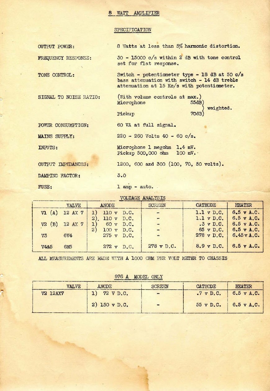
PHILIPS 976B SCHEMATIC & TECHNICAL MANUAL

PHILIPS 976B SCHEMATIC

PHILIPS 976B SCHEMATIC & TECHNICAL MANUAL

PHILIPS 976B SCHEMATIC & TECHNICAL MANUAL

PHILIPS 976B SCHEMATIC & TECHNICAL MANUAL

PHILIPS 976B SCHEMATIC & TECHNICAL MANUAL

PHILIPS 976B SCHEMATIC & TECHNICAL MANUAL


Saturday, July 20, 2024

SUPRO: Super Six, Model S6606 Valve Amplifier

Valco made, Supro single-ended valve amp, very much the same as the Gretsch 6150 / 6151


SUPRO SUPER SIX, MODEL S6606

12AX7, 6V6, 5Y3
8" Jensen speaker, 3.2 ohm
OT 2640
PT 3036
B+ 300v
4.5w
Supro S6606 single-ended valve amp schematic

SUPRO S6606 amplifier


Thursday, July 18, 2024

SELMER: Corvette, Little Giant & Mercury


SELMER CORVETTE 

Selmer Corvette amplifier schematic


SELMER LITTLE GIANT MKI & MKIII

Selmer little giant schematic mki


SELMER MERCURY 5

Selmer Mercury 5 amplifier schematic

Selmer Mercury 5


GRETSCH: Model G6151 & G6150 guitar amplifiers

Two great little guitar amps made by Valco for Gretsch - probably best to describe them as direct competition for the Fender Champ, but with some fancier appointments for the time.   Pretty sure there's a Supro equivalent that was also made by Valco for these two as well. Supro 1606 for the 6150.

Both small single-ended amps with an 8" speaker. 

Some was nice enough to upload a bunch of detailed photos, schematics and their layouts for the 1606 on their google drive located here

GRETSCH, MODEL G6150 AMPLIFIER SCHEMATIC

12AX7, 6V6GT, 5Y3GT
Jensen 8" speaker 
500k volume control
OT 2640
PT E-3036

Gretsch model 6150 amplifier schematic


GRETSCH, MODEL G6151 AMPLIFIER SCHEMATIC

12AX7, 12AX7, 6V6GT, 5Y3GT
8" speaker
500k volume & tone control
500k speed control
OT 2640 for 3.2 ohm speaker
OT VAC109 for 8 ohm speaker
PT E-3036
Gretsch model 6151 amplifier schematic


FENDER: Tweed Princetons

I'll start with the Fender 5F2A Princeton, as this is generally considered to be "the one" for a lot of people.

Basically take a tweed Champ, and add the classic Fender one knob tone control, which has no insertion loss, and you're in business.  It's hard to go wrong with this formula, which is why it appears in so many amps.  

FENDER TWEED PRINCETON - 5F2A, SCHEMATIC & LAYOUT

  • 12AX7, 6V6, 5Y3

  • Classic Fender hi / lo input stage
  • Standard Fender preamp component values / biasing 

  • Preamp is cathode biased
  • Volume 1M, Tone 1M
  • 22n coupling caps
  • 22k negative feedback from OT secondary to second triodes cathode 
  • Simple heater wiring - one side grounded


FENDER PRINCETON - 5B2 SCHEMATIC

  • Preamp is grid leak biased
  • Simple heater wiring - one side grounded
  • 6SL7, 6V6, 5Y3
  • Jensen P8T
  • Volume & tone 1M
  • OT 7765
  • PT 6500


Fender Princeton 5B2 Schematic


FENDER PRINCETON - 5C2 SCHEMATIC

  • 6SC7, 6V6, 5Y3
  • 2 x triodes in preamp - the first feeds the second via a voltage divider to reduce gain
  • Shared cathode resistor
  • Volume & Tone 1M
  • Volume & Tone control is sitting on the grid of the 6V6
  • Simple heater wiring - one side grounded


Fender Princeton 5C2 schematic


FENDER PRINCETON - 5D2 SCHEMATIC

  • 12AX7, 6V6, 5Y3
  • Preamp grid leak biased
  • Volume & tone 1M - 1meg resistor in series before the volume pot
  • No negative feedback
  • Simple heater wiring - one side grounded


FENDER PRINCETON - 5E2 SCHEMATIC

  • 12AX7, 6V6, 5Y
  • Classic Fender hi / lo input stage
  • Preamp is cathode biased

      • Volume 1M, tone 250k
      • Slightly more complicated tone control - tone control sits on the first triode's plate, before the coupling cap
      • Simple heater wiring - one side grounded

      • Choke on power supply
      • 22k negative feedback


      FENDER PRINCETON - 5F2 SCHEMATIC

      Almost identical to the 5E2 - no bypass cap on the first triode

      • 12AX7, 6V6, 5Y3
      • Classic Fender hi / lo input stage
      • Preamp is cathode biased
      • Volume 1M, tone 250k

        • Slightly more complicated tone control - tone control sits on the first triode's plate, before the coupling cap

        • Simple heater wiring - one side grounded
        • Choke on power supply
        • 22k negative feedback


        FENDER: Tweed Champ Schematics

        I know these are everywhere, but humour me - this is mainly for my own reference.

        FENDER CHAMP-AMP,  5C1 (WIDE PANEL TWEED)

        Note: The Fender Champion 600 and 800 are said to use the same schematic (or at least extremely similar).

        Preamp: 6SJ7 pentode, grid-leak biased (no cathode resistor)

        • Inputs: two jacks, each 75k in series with 0.02uF (20nF) into the grid

        • Grid leak: 5M to ground

        • Plate resistor (Ra): 250k

        • Screen feed: 2M, bypassed with 0.05uF (50nF)

        • Coupling cap to volume: 0.02uF (20nF)

        • Volume pot: 1M

        Power stage: 6V6 single-ended, cathode biased

        • Cathode resistor (Rk): 500 ohms, bypassed with 25uF

        • Grid leak resistor = volume pot

        Output transformer:  Triad 70189 

        Note: I can't find a definitive source of original Champ OT measurements.
        • Small single-ended output transformer
        • OT Secondary 3.2 ohms 

        • OT Primary, usually quoted as ~5k-7k  (some modern replacements offer 5k & 8k primaries). 

        Turns ratios

        • 46.8:1 = 7k @ 3.2 Ω    15VAC on primary = 0.3205 on secondary
        • 39.5:1 = 5k @ 3.2 Ω   15VAC on primary = 0.3797 on secondary


        Rectifier: 5Y3

        Power supply filtering:

        • 8uF reservoir → 500 ohms → 8uF (plate/OT node) → 25k → 8uF (screen + preamp node)

        Power transformer:  Triad 6500

        Typical Voltages:  Actual voltages vary a lot with wall voltage, rectifier condition, and transformer, but the commonly quoted targets for a 5C1 are roughly:

        Rectifier DC output (first B+): 340V

        B+ after the 500 ohm dropper / main supply node: 320V

        6V6 plate: 300V

        6V6 screen: 280V (lower because it’s fed through the 25k drop)

        6V6 cathode: 16V across the 500 ohm resistor (so ~32mA cathode current as a rough check)

        6SJ7 plate: 130V

        6SJ7 screen: 21V

        6SJ7 grid: -5V

        Heaters:  Simple wiring, one side grounded (not twisted pair, no centre tap)

        Speaker (stock): 1x6" alnico - commonly Permaflux 6-L (EIA 395), though other 6" period speakers exist due to Fender’s supplier variability and decades of replacements.


        Fender Champ 5C1 schematic


        Fender Champ 5C1 layout


        FENDER CHAMP 5D1


        FENDER CHAMP 5E1

        The classic Fender 12AX7 input stage and preamp values are used.  Negative feedback appears.  Choke on the DC power supply.  Changed to a regular component board; controls now on the top of the amp.

        Preamp: 12AX7

        Inputs: two jacks in the classic Fender input network.  When using input #1, the effective grid-stopper is about 34k because the two 68k resistors end up in parallel

        • Each jack feeds the grid through 68k
        • Grid leak: 1M to ground


        First gain stage (V1A):

        • Plate resistor (Ra): 100k
        • Cathode resistor (Rk): 1k5, bypassed with 25uF
        • Coupling cap to volume: 0.02uF (22nF)


        Volume control:
        • Volume pot: 1M (between stages)

        Second gain / driver stage (V1B):

        • Plate resistor (Ra): 100k
        • Cathode resistor (Rk): 1k5, not bypassed
        • Negative feedback: from OT secondary back to this cathode via a 22k resistor
        • Coupling cap to 6V6 grid: 0.02uF (22nF)


        Power stage: 6V6 single-ended, cathode biased

        • 6V6 grid leak: 220k
        • Cathode resistor (Rk): 470 ohms, bypassed with 25uF
        • Screen supply: taken from the main B+ node, after the choke


        Rectifier: 5Y3GT

        Power transformer: Triad 6500

        Power supply filtering:

        • On 5E1, the choke sits where the 5F1 uses a 10k dropping resistor

        • 8uF reservoir → choke → 8uF (main plate/screen/OT node) → 22k → 8uF (preamp node)
        Typical voltages (ballpark):

        • Main B+ node often lands around ~305V in many examples (varies with wall voltage and rectifier condition)
        • 6V6 cathode: ~19V across 470Ω (≈40mA cathode current as a rough check)
        • Preamp supply in many references is around ~260V


        Speaker (stock):

        Commonly a small 6" alnico in early narrow-panel Champs, often a Permaflux (though other 6" period speakers exist due to Fender’s supplier variability and decades of replacements)

        Fender Champ 5E1 schematic


        Fender Champ 5E1 layout


        FENDER CHAMP 5F1

        Almost identical to the previous model, with a 10k resistor replacing the choke.  While there is no bypass on the first triode, this is considered to be a mistake on the schematic.  Apparently lots of vintage amps have the bypass installed from the factory (visible in the photos below).  

        Fender Champ 5F1 schematic


        Fender Champ 5F1 layout

        FENDER CHAMP 5F1 chassis

        FENDER CHAMP 5F1 output transformer