Showing posts with label TOOLS. Show all posts

Tuesday, April 27, 2021

Getting Started Building DIY Guitar Effects - What You Need

After a couple of posts about workbench tools etc, I thought perhaps it's time for a guide on where to start, as the internet is a big place full of opinions (now including mine).  

Sometimes it's hard to work out what one actually needs and why they are needed.  The idea of saving money by building your own pedals might soon disappear.  

THE BASICS REQUIRED FOR ANY DIY GUITAR FX BUILD

You can't finish a build without these;

  • a soldering iron - ideally one with a stand, replaceable tip and adjustable temperature in the 30-50w range.
  • a tip cleaner for the soldering iron.  I prefer a brass cleaning ball over the damp sponge.
  • solder - I use 0.71mm as I find it more precise than the 1mm variety.
  • flux - you will make mistakes that need to be unsoldered and re-soldered.  Without flux, this becomes a nightmare.  Watch this video if you are unsure about the wonders of flux.
  • a solder sucker or desoldering braid - see comment above; mistakes will be made.  Get a semi-decent solder sucker; the cheap ones are frustrating to use.
  • small pair of side cutters and a pair of pliers (which can double as wire strippers if you are really, really careful).
  • wire strippers.
  • jewellers screwdrivers.
  • small craft or Stanley knife.
  • spanners or a smaller shifting spanner.
  • a drill with a stepped bit if the enclosures you're using are not pre-drilled.
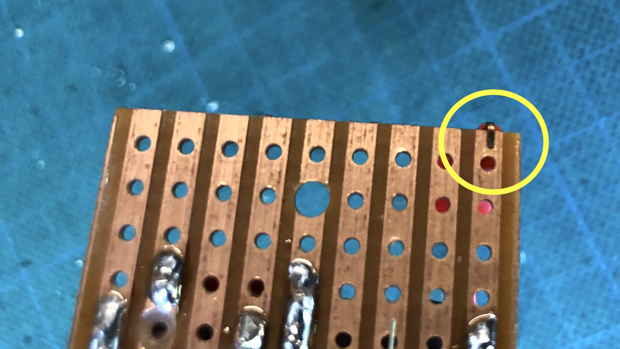
  • a magnifying glass - this is essential when starting out unless you have amazing eyesight.  This is for checking the solder side of vero boards to ensure that there are no solder bridges and, in some cases missed components.  It's easy to miss the leg of an IC socket on a crowded board.
  • for safety reasons, I probably should also mention an extractor fan.  Breathing fumes is not good for your health, probably quite bad.


TIME FOR TESTING YOUR CIRCUIT

Now, this is where it gets more interesting.  While the tools above will get a basic build done, if anything goes wrong, which it inevitably will at some stage, nothing there will help you test the circuit and find faults.  

This becomes really apparent when staring at your first build, wondering why it doesn't work, and not having a clue where to begin.

Basic test equipment;

  • a  digital multimeter - ideally one with a continuity tester (it beeps if things are connected).  An expensive multimeter is not required for guitar pedals. 
  • an audio probe (google it), unless you have an oscilloscope; this is the only way to follow the signal path in an attempt to find out where things have gone wrong.

When asking for help on forums / social media, the first thing people usually want is photos, a schematic/build docs and voltages on semiconductors.  And for a good reason too. 


NEXT STEPS

So now you have the basics sorted - things are going well, but you'd like to build something with germanium transistors, and the internet is yet again full of opinions and magical terms such as leakage and hfe.  

A multimeter just won't cut it when measuring germanium transistors, and for the most part, they don't do a very good job on silicon either.

There are two affordable choices;

  • a cheap multi-function tester - link to tester here.   These things are so cheap one could easily assume that they don't work.  Well they do, and for the money, they're great.  They test all sorts of things, including diodes, capacitors, resistors etc.

Either of these will tell you enough about your transistors to give you an idea of how they shape up.  Nothing beats testing them in the circuit, as I have often found that the transistors that are supposedly the 'wrong' transistors actually work just fine and sound great.


FURTHER DOWN THE RABBIT HOLE OF DIY EFFECTS

By now, you probably realise that making pedals may not have actually been a cheaper option than buying them after all.   So what next?

  • get a breadboard - why?  testing before committing to soldering becomes really obvious once you make a few pedals and start to test different components, fine-tuning them to suit your taste.
  • make a test rig - well, if you have a breadboard, you need a test rig right?  Everyone seems to have their own way of building a test rig - it's basically some form of enclosure that's easy to plug into your amp and attach the circuit to before boxing a circuit or while it's still on a breadboard.

BUT WAIT, THERE'S MORE

This is like the holy trinity of non-essential and potentially expensive tools.  They make the experience of building pedals just that much better - I think they are worth it if you have the space, money and intention to build a lot of pedals. 


MISCELLANEOUS EXTRAS 

  • a heat gun
  • extractor for solder fumes 
  • a work lamp
  • a small test amp that you don't care what happens to it, and/or a small monitor speaker
  • circuit clamp / strange third-hand clamp things 
  • a craft mat for cutting / working on
  • an old laptop / PC on your workbench, as you will be googling all sorts of things while you work out where you went wrong, or just for looking at layouts while you build them
  • and a bunch of other things that I can't remember right now, miscellaneous accessories that you will no doubt want along the way - I'm not even going to go near component storage


WHAT TO BUY & WHERE TO BUY PARTS FOR PEDALS

A common question and this is really too much to even try and answer, but I will leave you with some simple advice.

  • there's nothing wrong with using plain old 1/4watt metal film resistors - they're cheap and plentiful
  • greenie caps are fine, as are regular box caps and MLCC - like metal film resistors, there's nothing wrong with generic capacitors from a good quality supplier.
  • check the physical dimensions of capacitors before buying them, as you might mistakenly buy huge ones that don't fit (large voltage ratings can be a giveaway for this, especially for electrolytics)
  • don't buy JFETs, germanium transistors or germanium diodes off eBay from China - from my experience they are often fake
  • don't stress about having the exact part number for standard silicon transistors, as it hardly ever matters, so long as they're similar hfe (broadly low, medium or high gain)
  • Tayda is fine for most things
  • RS Electronics is great if you live in Australia.  I also resort to local stores that clearly have a lot of cheap imported parts sold at a hefty markup (Jaycar).  Altronics is a step up from Jaycar if you have one nearby.

Monday, April 5, 2021

Bench Power Supply

Perhaps not often talked about in the world of guitar pedal building, as they’re kind of boring as all hell - the humble bench power supply.   So why am I bothering you with this?

Apart from being able to dial in most voltages that I need, a bench power supply is actually a handy tool in other ways.  As soon as I turn it on and see the current fluctuating or pulling more current than it should be, I know I have a problem with the circuit.

They’re also safer than using a battery, as there’s actually potential for batteries to get really hot and explode if you have a short on the supply and leave them for some time.  

So if you don't have one and are wondering what's the point when a wall-wart or a 9V battery will do for most things...   well, maybe consider one if you see it going cheap.


bench power supply for testing guitar pedal circuits


Monday, January 18, 2021

SMALL BEAR: Germanium Transistor Test Method

Given I listed the RG Keen method, I thought I should add the Small Bear method as well.  It's a simpler test that some people prefer, and it's generally considered not as accurate as the RG Keen method but close enough for most purposes.

NOTE:

  • Be prepared to see the voltage fluctuate a lot while the transistor stabilises.  Don’t wait too long though, as you will be there forever - it may never stop!  
  • Handle the transistor as little as possible with your fingers, as the heat will transfer
  • Different environments will provide different results - this is very temperature dependant 
  • With all methods, the test results will vary, depending on the method used.  Why?  Without attempting to explain the math that I don't fully understand, hFE varies with the current applied to the base.  Different test methods and test equipment apply different currents, so results will differ.
Small Bear germanium transistor test method


Sunday, January 17, 2021

IC Test Clips, Vero Clamps

I discovered this nifty little hack today, maybe you already know about it, but it's new to me.

After improving my germanium transistor test kit yesterday, I thought I should also upgrade some dodgy leads I’ve been using with my breadboard.  

I sometimes start building on vero, then solder wires on temporarily to test different component values on the breadboard.  While it works, it was messy and time-consuming, and it turns out there's a much easier way to do this (at least for edge connections).   

I bought some IC test clips and wired them up for the breadboard.   As it turns out, the IC clips aren’t just good for ICs - they also grab the edge of vero board quite tightly, making them perfect for testing without resorting to tacking on wire.

At nearly 60mm long, these are a decent size clip and are quite sturdy.  The smaller 30mm version still works; they are just less stable and feel less solid.


The stock clip doesn’t fit through veroboard holes, but I did manage to bend one of the smaller clips slightly, so it will go through holes and clamp anywhere on the board.  Very handy indeed.


The stock clip is on the left and modified on the right.


Saturday, January 16, 2021

TRANSISTORS: RG Keen, Germanium Transistor Test Method

If you haven't heard of this before (which seems unlikely), here's the original RG Keen article, which explains how it works.  I use a spreadsheet set up with the calculations ready to go for testing; there's also an online calculator here.


NOTE:
  • Be prepared to see the voltage fluctuate a lot while the transistor stabilises.  Don’t wait too long though, as you will be there forever - it may never stop!  
  • Handle the transistor as little as possible with your fingers, as the heat will transfer
  • Different environments will provide different results - this is very temperature dependant.
  • With all methods, the test results will vary, depending on the method used.  Why?  Without attempting to explain the math that I don't fully understand, hFE varies with the current applied to the base.  Different methods apply different currents, so results will differ.

RG KEEN METHOD FOR TESTING GERMANIUM TRANSISTORS

RG KEEN germanium transistor test


LEAKAGE TABLE FOR RG KEEN METHOD

If you just want to know how leaky the transistor you’re testing is, here's a quick guide (numbers have been rounded for ease of use).  This only applies to the RG Keen method.

VDC        LEAKAGE - uA
0.1           40
0.25         100
0.5           200
0.75         300
1.00         400
1.25         500
1.50         600
1.75         700
2.00         800


TESTER BUILD

I recently purchased a small multi-function tester, and while it's great for so many different measurements, I wasn't completely happy with the leakage results on germanium transistors - maybe it's just not what I'm used to...   

I've been using a tester that I built using a layout from Guitar FX Layouts  and while it works, it's very small, and I found that the transistor socket got a bit loose over time.  It was just a bit fiddly for me.  

So today, I built something a bit more robust from some scrap 0.15" vero, I kind of worked it out as I made it, so the layout below is not an exact match.  

  • Pins to insert in a breadboard rather than use a socket
  • The switch is mounted through the board, and I used a trimmer for biasing the collector

It's not the best-looking thing I've ever made, but it feels solid, and it works as intended.  I wish I had more colour options for the wires and shrinkwrap to make it easier to identify the leads, but it's not the end of the world.   I might even get around to mounting it in an enclosure one day with a small breadboard attached.


This is a rough layout, not identical to the one I made, but you get the idea.  

NOTE:  
  • This is specifically laid out for PNP germanium transistors; if you want to measure NPN, reverse the polarity of power and the multi-meter
  • Components must be as close as possible to the values provided to provide the most accurate results (including voltage)

Friday, January 15, 2021

Multi-Function Tester TC-1

I picked up one of these little testers off eBay for AUD$25 recently, and it arrived yesterday - my first impression is that it's pretty good for the price.

Previously I have been using the RG Keen method for testing germanium transistors, using a little test circuit from Guitar FX Layouts and a multimeter.  

There's also a handy online calculator that can be found here to provide results.  It works pretty well, and it's certainly the cheapest option available.  

This is great for germanium transistors, but what about everything else?  I bought a job lot of old transistors a while ago (germanium and vintage silicon), and quite a few of the vintage silicon are unidentifiable.  

What I was lacking was a way to quickly identify what the random transistors are in terms of type, pinout and hFE.  My multi-meter has a hFE test, but you have to know the pinout and type of transistor being tested - it's next to useless....    This cheap little tester fills that gap.


What can it test / identify?

  • BJT Transistors
  • MOSFET / JFET
  • Diodes
  • Resistors
  • Capacitors
  • Inductors
  • + Thyristors, Triacs and low-voltage batteries


Easy to use

  • Attach the component in and turn it on - wait a few seconds, and the result will appear.
  • It identifies the part; there's no need to give it a range to tell it what to measure.

  • The small colour screen is easy to read, just large enough to do the job.


But.....

So I grabbed a few transistors to test, and found the leakage results to be a little different between test methods.

The results below are for a Valvo OC75, taken directly from one test to the other, with minimal time and handling between tests (all handling was done with small pliers).  It was 30 degrees Celsius / 86 Fahrenheit, a pretty standard summer temperature where I'm located.

Note that the hFE is close enough the leakage is off by 76mA (0.526mA vs 0.450mA) - which is not a huge amount, but enough to annoy me over the inconsistency.  

As it turns out, this is relatively common, as different test methods apply different amounts of current to conduct the test, resulting in different outcomes.


RG Keen method

First reading = 1.3v
Second reading =  2v
1.3 / 2.472 = 0.526mA leakage
(2 - 1.3) * 100 = hFE 70


Multi-function tester

hFE = 73
Ube = 109mV
Ic = 1.2mA
Iceo = 0.45mA (this is leakage)
Ices = 31uA