Since I'm doing boosters at the moment - the D*A*M Supa Rooster.
I'd suggest placing a 1m resistor on the input and output if you get switch pop - a lot of people do this all the time for their rangemaster type circuits. If you want it to look true to the original, use 1/4w metal film resistors and sneak them under the board.
Pretty much the same layout as the D*A*M pedal, can't see the value on a few components, but safe to say, that anything in the normal area of a rangemaster will be just fine. I'm talking pot values and the smaller input capacitor in particular.
It's no secret as to what the R2R Electric germanium preamp is based upon, which is an old and very rare Hofner preamp. The Hofner is a full-range germanium booster, which was once used as a way to plug guitars into old console radios way back in the day.
As this is a simple Rangemaster style circuit, any layout used for a Rangemaster could be used instead of the one below.
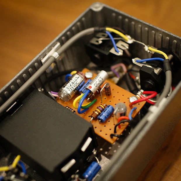
R2R ELECTRIC GERMANIUM PREAMP LAYOUT
R2R spends a bit of time testing every component used, to get the sound that they're chasing. Since not all components are created equal, it’s worth dedicating time to testing and selecting components to ensure you get the most out of this simple circuit.
One notable choice is the AC107, which R2R recommends as a low-noise, higher-quality alternative to the OC44 or OC71 commonly used in Rangemasters. This decision is practical: while OC44s are highly sought after due to their use in Rangemasters, they’ve become increasingly expensive and are often prone to noise issues.
Side note: An excellent podcast featuring Chris from R2R can be found here on the Fretboard Journal. Chris talks about his journey and process.
And thanks to the person who very kindly helped out by sharing some photos of their pedal, confirming that the boost pot is wired the same way as a Rangemaster.
I built it on tag strip, using the same layout - works just fine. If you do the same, careful with the size of the caps either end as it’s a very snug fit in a 1590B
Boost / Volume pot: R2R implemented the volume/boost control in the same way as the Rangemaster. The stock Hofner circuit uses a 10k resistor to the collector and has no volume control - R2R replaced the 10k resistor with a 15k pot. If a 15k pot is hard to source (as it's an uncommon value), try a 25k pot with a 39k resistor across pin 1 & 3 - this will drop it down to 15k. Any resistor between 33k - 50k will get you close enough to 15k. Pots are rarely bang on spec, so not something to stress about. You could also experiment with a 10k pot to see how it goes.
Input resistor: There's no need to worry about using the exact value for the input resistor. The stock Höfner schematic specifies 37k, which is an unusual value. R2R opted for 36k. As long as your choice is close, it should work fine.
It’s worth noting that the input resistor forms a voltage divider with the 10k resistor connected from the transistor base to ground. Together, these resistors reduce the input signal by about 80% before it’s amplified by the transistor.
Emitter resistor: The stock Hofner circuit uses a 1k5 emitter resistor, but there's room for variation, which can be tuned to match your chosen transistor. The R2R layout uses a 3k9 resistor, like the Rangemaster. Smaller values are more likely to produce some dirt, while larger values will result in a cleaner sound. This is a great spot to use a trimmer pot if you want adjustable control.
Capacitors and Bias Resistors: The capacitor values and the 100k/10k bias resistors remain consistent across designs. However, there's flexibility with the capacitor values:
The input capacitor can be reduced significantly without noticeable changes in response. For instance, 1u is nearly indistinguishable from 4u7.
The 100u emitter bypass capacitor can be reduced to 47u with minimal impact.
Similarly, reducing the output capacitor slightly will have negligible effects on the sound.
Of course, collectively changing a lot of component values at once will increase differences, but ultimately, it is just a fairly generic single transistor booster in therms of the circuit.
Drop down resistors: R2R included 1M input and output drop-down resistors wired to the stomp switch, which you can see in the photos below. These are not present in the Höfner circuit but are a common addition to prevent switch pops. Including them is recommended.
Board: I’ve not listed the size of the board or any other info on the point-to-point layout - I’m sure you can work that out yourself.
Images below from a prototype - the 1k5 resistor may not have made it into production models.
Here’s a simple Rangemaster treble booster. I’m jotting down some notes from my recent builds because I really dig this layout. I used a 1590BBS enclosure and an 8-way tag strip. It’s pretty similar to the Pigdog Eel Pie layout, which inspired my design.
Inside, you’ll find a Mullard OC71 transistor. But honestly, the specific transistor isn’t a huge deal—pretty much any PNP germanium transistor will sound great in a Rangemaster. You definitely don’t need an OC44 to get that sweet sound.
What really makes this pedal shine is a couple of key factors:
Hitting Your Valve Amp Hard: The Rangemaster works best when you crank it into the front of a valve amp.
Adding Harmonic Distortion: That germanium transistor adds some nice harmonic distortion, which enriches the overall tone.
For the best results, pair it with a valve amp that’s just on the edge of breakup or slightly dirty - there's always a bit of a balancing act between the amp and the boost level. Once you find your happy place, set and forget. Keep in mind that once the amp is clipping, it doesn't really get louder, it gets more saturated, and some bass is trimmed off the signal - for many people, this is the sound that they're looking for.
If you run it into a super clean amp—especially a solid-state one with lots of headroom—you won’t get great results, as it just sounds thin.
Which looks like this in practice.
There's just enough room in there for a battery, but I decided to skip it for this one.
Just a Rangemaster with a rotary switch for selecting input capacitors - it uses some odd parts, as this is what was available in my local electronics store - the 5 lug tag strip in particular, a regular Rangemaster is on 6. It's also a slightly odd rotary, but it was all that was left in the draw.
RANGEMASTER BASED GERMANIUM BOOSTER - VARIABLE FREQUENCY
You may also want to add a small cap ( 470p / 1n) across the input to the base of the transistor, so there’s always a capacitor in the circuit - this reduces switch noise on the rotary. I don’t think it’s massively important, as I’m a set and forget kind of guy.
Do check the numbering on the rotary, as the ones that Ive been using are in reverse, compared to the layout. i.e. start with small cap values on the left.
Expect some hiss - this circuit is infamous for it, but it does sound good so most people overlook this. Having a rotary with a few capacitor options is so much better than the stock Rangemaster treble booster - the additional range of sounds is well worth it. The full range boost can get a little fuzzy, which is something that I was not expecting.
While it was pretty quick to put the Rangemaster board together, it wasn't fast to wire up the rest. There was a bit of fiddling with lining up the capacitors on the rotary, and the general position of the tag strip didn't help matters.
Same again, but this time with a pot to help set the gain, instead of a 3.9k resistor. This is hand to dial in (or out) the grit that can really make treble boosters shine.
I came across this while browsing one of the usual forums recently and thought it looked like an interesting Rangemaster variant. Silicon or germanium transistor, variable boost, quiet, standard power supply... seems to have a lot going for it as far as treble boosters go.
The Earthquaker Devices Bows is a straight-up germanium Rangemaster with some modern tweaks. It uses an NPN transistor and has a switch to swap to a larger input capacitor for a full-range boost.
The space above the transistor on this layout allows it to be mounted on its side (bent over 90 degrees), as OC transistors are pretty tall, and if you use the mounting points, you will need to reduce the height of the transistor in the enclosure. It's generally a good idea to place insulation on the legs of the transistor so they don't short when you bend them. If not all the legs, at least the base leg in the centre of the three.
A bit of a classic - well one of the first guitar effects really, the Dallas Rangemaster. A nice simple one for a quick build using leftover tag board.
In theory there is room to fit the output cap on the board too, but I liked the straight lines of the components.
DALLAS RANGEMASTER TREBLE BOOSTER - TAG BOARD LAYOUT
While I was thinking of what could be made with tag board off-cuts, this popped into my head.
The D*A*M Red Rooster Booster is probably my all-time favourite booster - I've only ever made one, and it was so good I stopped there (it was a point-to-point npn version with trimmer).
This is a PNP version; the 3k9 resistor could be swapped for an upright/inline trimmer.
D*A*M RED ROOSTER BOOSTER - TAG BOARD LAYOUT
Fun fact: In Australia Red Rooster is the name of a cheap roast chicken franchise.
I've already done a point to point layout for the D*A*M Red Rooster Booster (which I love by the way), but as I'm on a run of D*A*M layouts today, I thought I might do this one too. Like the rest, this is not my layout; it's a close copy of the D*A*M layout. If you want to stay true to the look, hide the jumper under the board.
This is the PNP version, which can easily be changed to NPN if you prefer by flipping the electrolytic caps.
I noticed in one photo, a resistor to ground from the 10n output cap. Maybe there was some pop that needed to be dealt with? Anyway, squeeze that in between the two electrolytics if you need or want to try that. I couldn't make out the value... 1meg has worked for me in the past.
Try setting the trimmer to 3.9k to start with, as that's the standard value for a Rangemaster Treble booster, which this of course is a variation on. Someone once asked David Main about bias voltages - he suggested 6.66v - no doubt a little joke on his part, but it will get you close. This is one that you can happily bias by ear; it seems fairly forgiving, at least it was on my other build.
A variation on the classic Rangemaster Treble Booster from D*A*M. The Red Rooster germanium booster uses a NPN transistor so it can run off a normal power supply, and features a capacitor blend on the input to sweep between treble boost and full range boost.
This has a lot of boost on tap - it will crush anything it's put in front of. It's also happens to sound great, so I'd recommend building it if you have the parts spare and valves to punish.
There's an excellent article here from R.G. Keen as to how a Rangemaster works, including bias voltages and transistor selection. Electrosmash also has a very detail explanation.
D*A*M RED ROOSTER BOOSTER - POINT TO POINT LAYOUT
NOTE: Stock trimmer setting is 3k9 for a Rangemaster.
D*A*M RED ROOSTER BOOSTER - ON THE BENCH
Not exactly parts as per schematic. I used a 2n7 instead of a 4n7 cap and a 30k trimmer instead of a 5k trimmer as I had a spare sitting right in front of me at the time that I thought I might use instead.
I used an old AC176 NPN germanium transistor with axial and tropical fish caps for added mojo. It sounds killer, which apart from the additional gain, I think is the AC176 working its magic.
D*A*M RED ROOSTER ON THE SCOPE
Signal source: 440hz sine wave, approx 130mv TRMS
Range 0%, with a fair bit of boost (can't remember where it was exactly). There's still more boost available, I stopped here before it started to clip the sound card input on my laptop.
Range 50%, with boost pulled back
Range 100%, still quite a bit of boost left, as mentioned above, I stopped so as to not clip the sound card. It's getting pretty dirty by this stage, producing a lot of harmonics.


