Showing posts with label MODS. Show all posts

Sunday, June 23, 2024

VOX: AC4C1-12 Transformer Upgrade

Before I completely rip this Vox AC4 apart and rebuild the amp on tagboard, I thought I'd try swapping the output transformer (OT), just to see if it made any difference to the sound of the amp, as I've read conflicting views online.  

Cutting a very long post short - yes it did make a difference, it sounds much better in my opinion.  I'd already snipped the bright cap (C20) on the master volume and installed a vintage alnico speaker.  The transformer upgrade rounds things out very nicely.  Running 16ohms @ 5k:  No fizz, it sounds bigger and more open sounding.  The amp is cleaner sounding and the breakup is nicer.  It somehow sounds less boxy, which I can't figure out - maybe increased frequency response??  16ohms @ 10k is closer to the stock transformer spec, so some of the original tone returns - I much prefer 16ohms @ 5k.  

VOX AC4 OUTPUT TRANSFORMER SPECS

There's almost no information available on the stock Vox OT apart from the factory part number and that it's made in China.   I did a quick test after I pulled it out, and I found that it has a ~22:1 wind ratio.  With a 16ohm speaker, this puts about 7.4k on the EL84.  An 8 ohm speaker will drop this down to about 3.7k.  

A few forums posts say that it's 10k, I can only go off my own measurements. 

Wattage unknown - safe to say that it has to be at least 4 watts given the rating of the amp.  I'm going to take a guess and say that it's a little over-rated as it's a similar size to the Hammond, which is 8 watts.  Unlike the Hammond, there's no additional taps on the secondary.

Vox AC4 - stock output transformer vs Hammond 125CSE

Vox AC4 - stock output transformer vs Hammond 125CSE

HAMMOND 125CSE OUTPUT TRANSFORMER SPECS

I decided to use a Hammond 125CSE as it was available locally at a reasonable price, and the specs looked right.  Hammond transformers are made in Canada and seem to be quite well regarded (completely unrelated to Hammond organs by the way).  

The Hammond 125CSE is an 8w transformer - it has similar dimensions to the stock OT - conveniently the mounting is the same width, so no additional holes were required.  The Hammond felt a little bit heavier and generally speaking seems to be a better build quality.  It certainly sounds better.

There's plenty of information available on Hammond output transformers, the most important of which is on the diagram below.   By way of comparison to the stock OT, the 125CSE can run at 16 ohms with 5k on the EL84.  This is closer to how an EL84 is designed to operate.


Hammond 125CSE output transformer winding diagram

Hammond output transformer 125CSE frequency response

Hammond output transformer 125CSE frequency response

VOX AC4C1-12 OUTPUT TRANSFORMER UPGRADE

WARNING:  VALVE AMPS CONTAIN VERY HIGH VOLTAGES - LETHAL VOLTAGES CAN BE PRESENT, EVEN WHEN THE AMP IS DISCONNECTED FROM THE POWER.

I've marked up a few relevant items on the AC4C1 circuit board.  Both the 10" and 12" version are the same.

Vox AC4-C1 circuit board

In very simple terms,  I disconnected and reconnected P2, P8, P10 and P11 on the schematic below, with a replacement transformer and the addition of a rotary switch to allow three options on P10.

Vox AC4 schematic - output section


The first step is to remove the back of the amp - I like to leave the chassis on the back of the enclosure, as I find it easier to work on this way.  Naturally the amp is not plugged in at this stage, and hopefully has not been used recently (hot valves and potential for stored DC in caps).  Note that this mod involves the B+ supply to the EL84 - we're talking a 320V connection.  

The output transformer is connected to the board using fully insulated 1/4" 6.3mm female spades - these slide off, however some force is required to do this and the circuit boards are flimsy.  If you try this, take it slow and work very carefully.  

The primary connections to the output transformer are directly either side of the EL84 - there's very little room here.  I removed the EL84 before attempting to remove the spades connected to P8 & P2 using a combination of my fingers small pliers - a bit of gentle wiggling and force was required.

Same again for the secondary connections which are attached to the external speaker jack.  This board feels like it wants to snap off, and the spades face the large filter cap on the circuit board - not a great combination.   

Vox AC4 circuit board speaker connection

Note that there are actually 2 x P10 and 2 x P11 connections on the small circuit board that the extension speaker jack is mounted on - they're linked.  One pair from the OT, the other pair to the speaker.

Vox AC4 speaker connectionVox AC4 output transformer connections

After the wires were removed from the circuitboard, I removed the stock transformer.  Quick test placement of parts, before drilling the hole for the 3 way rotary switch.  Need to be really careful to make sure no waste from drilling the hole remains, as you don't want bits of metal sliding under that circuit board - boom!   

Vox AC4 transformer upgrade

I crimped new spades onto the Hammond transformer leads and bolted it onto the chassis - I did not trim the leads to the correct size, as I plan on rebuilding this amp at some stage.  I didn't want to cut anything short.  I used heat shrink to terminate the end of the unused orange secondary wire.

The primary windings (blue and brown wires) attach to P8 & P2 on the circuit board.

I'm using a 3-way rotary for the secondaries to increase output options as shown below.  I wired the three secondaries that I needed to a 3 way rotary (white, yellow & green).   The common pin on the rotary connects to P10.  The black secondary connects directly to P11 on the external speaker board. 

I have no plans to detail this process any further - if you can't work out what I mentioned above on your own, it's probably not advisably for you to be playing with high voltages.


I'll add proper labels for the rotary at a later date - while I know what the coloured dots mean, if I ever sell the amp, this will need to be clear to avoid issues.


Thursday, October 6, 2022

FUZZ FACE: Output Level Mods

One of the most common complaints about a Fuzz Face is the low output level. For such a famous circuit, the usual output tricks do not seem to be especially well documented. The good news is that none of them requires changes to a standard layout.

The key thing to understand is that the usual Fuzz Face output is not taken straight from the collector of Q2. Instead, the output cap is connected to the junction of the 470Ω and 8.2k resistors.

A simple way to think about this is like a volume pot. Q2 generates signal across the full collector load, but the output is taken from partway along it, not from the end.  So the circuit is effectively turning its own signal down before it even reaches the output cap.

In stock form, the tap is very close to one end of that “pot”, so you only get a small fraction of the available signal. That is why the standard Fuzz Face output can feel lower than you might expect.

So the basic idea behind these mods is very simple: move the tap, or change the ratio, and you get more signal out — without necessarily changing the character of the fuzz itself.

FUZZ FACE MATH

Because the output is taken from the junction of the two resistors, the available output level is set by the ratio of the top resistor to the total collector load.

So the basic equation is:

Tap fraction = top resistor / total resistance

This is an idealised, unloaded ratio, but it lines up very well with what shows up in simulation.

Stock Fuzz Face

Top resistor = 470Ω
Total resistance = 8,670Ω

470 / 8670 = 0.0542

So the stock output tap sees about:

5.4% of the available collector-load signal

With 470Ω over 8.2k, the output only sees about 5.4% of the signal developed across the full 8.67k collector load.

So if the resistors were a pot - it would be turned 95% of the way down.

Standard 1k mod

If you change the 470Ω resistor to 1k, and leave the 8.2k alone:

Total resistance becomes:

1000 + 8200 = 9200Ω

Now the tap fraction is:

1000 / 9200 = 0.1087

So the output tap sees about:

10.9% of the available collector-load signal

That is almost exactly double the stock tapped output:

10.9 / 5.4 ≈ 2.0

This is why the standard 1k mod works so well. It is not magic, it just gives the output tap roughly twice as much signal to work with.   It does change the bias a little, but hey….   

Resistors swapped

Top resistor = 8200Ω
Total resistance = 8670Ω

8200 / 8670 = 0.9458

So now the output tap sees about:

94.6% of the available collector-load signal

Compared to stock, that is an increase by a factor of:

94.6 / 5.4 ≈ 17.5

So swapping the 470Ω and 8.2k resistors gives about 17.5 times the stock tapped output.

That is why it gets dramatically louder - this will be super hot, likely too hot for most.

Equal values

If the two resistors are balanced, say 4.3k and 4.3k, then:

4300 / 8600 = 0.5

So the output tap sees:

50% of the available collector-load signal

Compared to stock, that is:

50 / 5.4 ≈ 9.2

So an equal split gives about 9.2 times the stock tapped output, while still being much more controllable than the fully swapped version.   It’s still going to be very hot, but it can be quite cool for running the guitar volume wound back for sparkling clean tones, but still with a lot of level.  

Straight from Q2 collector

Not recommended - you are now taking the full available collector signal.   It’s a massive signal.  

So that is effectively:

100%

Compared to the stock tap at 5.4%, that is:

100 / 5.4 ≈ 18.4

So taking the output straight from the collector gives roughly 18.4 times the available stock tapped output.

This is the nuclear option in terms of output level.   


STOCK FUZZ FACE OUTPUT

Probably should start with a stock version as a reference.  Everything is set to full, and there's a healthy output level.  Happy days...  but not all Fuzz Face stories have happy endings, so read on.

200mv peak to peak in, about 430mv out

LTSPICE FUZZ FACE MODS


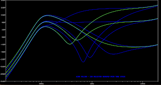
Here's the frequency response with the fuzz swept, which is how I'll do the rest of the comparisons.

LTSPICE FUZZ FACE MODS


And here's the standard schematic that we probably all know by now - note the voltages for comparison later.

LTSPICE FUZZ FACE MODS


R2 & R3 SWAPPED

A simple swap of R2 & R3 will increase levels quite dramatically - note the voltages compared to the stock schematic.

LTSPICE FUZZ FACE MODS

They look the same right - yes they do, but note the difference in scale on the voltages.  Now the output at the junction is a tad over 7 volts.   

LTSPICE FUZZ FACE MODS

The frequency response looks the same as the stock version

LTSPICE FUZZ FACE MODS


R2 & R3 MATCHED

This time the R2 & R3 values have been balanced - again, note the voltages compared to the stock schematic. 

LTSPICE FUZZ FACE MODS

Looks familiar right?
LTSPICE FUZZ FACE MODS

Now the voltage at the junction is about 3.5 volts - still very large, but only half of the method above.  But with a bit of experimenting or the use of trimmers, you can fine-tune this to a place that you're happy with.

I always like to question how much output a pedal really needs, as it seems to be a thing for modern pedals to have more output on tap than anyone would ever use.  Is all that unused gain just additional noise and a poor gain structure overall?

LTSPICE FUZZ FACE MODS


STRAIGHT FROM Q2

This is the nuclear option - this compares the stock output to straight off the collector.   It's massive by comparison.

LTSPICE FUZZ FACE MODS


So in conclusion - if you have low output Fuzz Face but really like the sound (which means you probably like the bias), maybe try one of these tricks before adding a trimmer, which will change the bias to Q2, and subsequently, the sound of the Fuzz Face.

This does completely ignore Q1, but this post was never intended to cover every possibility of the Fuzz Face.  


Monday, October 3, 2022

UNIVOX: Common Super Fuzz Mods

While cleaning up some old posts, I thought I might turn back on one of my old favourites - the Univox Super Fuzz.

Here are some common mods on LTspice.

STOCK SUPER FUZZ SCHEMATIC

STOCK SUPER FUZZ SCHEMATIC


TONE POT MOD


It's a nice simple one and the most common mod.  The tone switch is replaced with a pot to sweep between the notch and unfiltered outputs.  I think, in the process, this actually reduces the depth of the notch.


SUPERFUZZ NOTCH POT MOD


Another common mod - this time, the pot dials in the notch.  There is no unfiltered output, just varying degrees of the notch.


SUPER FUZZ DIODE POT MOD


This one can be a bit more subtle tonally, as it doesn't specifically effect the frequency response - the pot dials in a bit of extra resistance before the diodes hit ground.  Given the signal is already heavily clipped before it hits the diodes, this one is often referred to as changing the 'body' of the fuzz and is a little rougher around the edges.


Sunday, July 31, 2022

MARSHALL: Blues Driver / Boss Discrete Opamp

If you've read any recent posts, you may have noticed that I'm experimenting with discrete opamps - specifically replacing standard opamps with simplified discrete opamps - I've only played with the Joe Davisson diode compression opamp so far (with some success).

While I was checking out DIY Stompboxes, I saw Rob Strand was experimenting with the Boss discrete opamp that's used in the Blues Driver.  I've occasionally looked at it but have never gotten around to playing with it.  

Anyway...  it appears to work as a drop-in, and I thought a Blues Driver / Blues Breaker hybrid might be fun.  They are totally different circuits by the way - similar in name only.

More to follow on the Boss discrete opamp.  Feel like I need to spend some time playing with this and the Blues Driver.  I have an interesting idea in mind for the Blues Driver; I'll post it if it's successful.  


MARSHALL BLUES BREAKER X BOSS BLUES DRIVER DISCRETE OPAMP


It looks like a Blues Breaker on LTspice.  But I'm always a little suspicious of anything using JFETS on spice as they're notoriously variable beasts in real life.


BOSS BLUES DRIVER SCHEMATIC - OPAMP MARKED

Here's the Blues Driver schematic, with the discrete opamp marked. A good analysis can be found here if you are interested in further reading.  


Saturday, July 9, 2022

MI AUDIO: Discrete V2 Crunch Box

I'd already done the Blues Breaker in this format, and it sounded pretty good, so I thought why not try the MI Audio Crunch Box, as it's a high-gain derivative of the Blues Breaker.  

They have a similar topology - the Crunch Box has the soft clipping diodes removed and hard clipping LEDs added after the op-amps.  The LEDs probably just round things out a little, as the second op-amp is clipping hard. 

It looks pretty similar to the opamp version on LTspice, but with a bit less gain (which for me might be preferred).   I hope to get a slightly more dynamic distortion out of this compared to the stock MI Audio Crunch Box.  The stock Crunch Box is not really my kind of thing.

Untested at present - this is a future build file for me.  Try it if you want, but who knows what it will be like at this stage.


MI AUDIO CRUNCH BOX V2 - DISCRETE OPAMP VERO LAYOUT

MI AUDIO CRUNCH BOX V2 - DISCRETE VERO LAYOUT


MI AUDIO CRUNCH BOX V2 - DISCRETE OPAMP - SCHEMATIC

MI AUDIO CRUNCH BOX V2 - DISCRETE OPAMP - SCHEMATIC


Sunday, July 3, 2022

MARSHALL: Blues Breaker, Discrete Opamp Mod

I've had some success with the Joe Davisson diode compression discrete opamp on some other circuits (namely the Cornish SS-2), so I thought I might try a Blues Breaker - it works...  sounds good.  

Apart from the lack of IC, there are a couple of other minor mods to a stock Blues Breaker, mainly a larger input cap (Morning Glory) and some larger resistors on the inverted input of the first opamp (King of Tone).  I'd also recommend a C250k pot for gain, if you want more dirt (which is what I'm using).

I've increased the bass response on mine - all you have to do is change the 10n cap on the bottom row to something bigger, and you'll get some low-end back.  I like 220n, as it seems to keep all of the bass that I started with, but some might find this too much.  Could be cool to have this on a switch.  

For anyone with a keen set of eyes, you might notice the RC networks on the inverting input of the first stage going to ground instead of vbias - it was convenient to do on the layout, and it makes zero difference to the sound.   


DISCRETE OPAMP - BLUES BREAKER - VERO LAYOUT

DISCRETE BLUES BREAKER - VERO LAYOUT


DISCRETE OPAMP - BLUES BREAKER - SCHEMATIC

DISCRETE OPAMP - BLUES BREAKER - SCHEMATIC

And here's it looking a mess, but 100% working, attached to the breadboard - I made a couple of errors initially, so this is not exactly the same layout as above, as I fixed it on the fly.   Note to self: don't attempt creating layouts followed by soldering them when really tired.


VISUAL ANALYSER

440hz sine wave input

Scope taken on the output, with the volume turned down a bit.   Starts with gain on 100%, sweeps tone control up and down a couple of times, and then reduces gain.


The output of the first boost stage, gain 100% (note the input signal sits at -25)


The output of the clipping stage (gain 100%), before any filtering from tone controls and caps to vbias - it has a lot of harmonics / high-frequency content, and it's bordering on being a square wave.


Wednesday, April 13, 2022

GREER AMPS: Lightspeed X Southland Overdrive, Switch Mod

So given the Lightspeed and Southland are basically the same circuit, I thought I might add a switch to swap between the two.

The switch does three things;

  • Switches the hard clipping diodes in/out
  • Changes op-amp gain (to account for the hard clipping diodes)
  • Changes Drive pot resistance

While they use different op-amps, they're both just dual op-amps, so choose a favourite and run with it.  The Lightspeed uses an expensive high-performance op amp, and the Southland uses a standard TL072.

Schematics for both can be found over at PedalPCB, if you want to check out the similarities yourself.   

It's a little cramped now, but you can always add a row on the right-hand side to free up some space.

LIGHTSPEED X SOUTHLAND OVERDRIVE SWITCH MOD

LIGHTSPEED X SOUTHLAND OVERDRIVE SWITCH MOD


NOTE:  I've not tested this on the breadboard or LTspice, so I can't tell you if there are significant output level differences between the switch settings - I don't know if it would be a good idea to have the switch as a foot switch.  It might be awesome; I just don't know...  

Saturday, April 2, 2022

DIAMOND: Fred Briggs Diamanté Compressor

I was looking at the Diamond Compressor schematic the other day and thought it looked interesting and possibly something that could be simplified - it turns out it can be simplified.  Of course, someone had already done this.  Jump over to the La Revolution Deux for details, AKA Fred Briggs' blog.  

I used a TL074 instead of a couple of separate opamps for this one.


DIAMOND / FRED BRIGGS DIAMANTE COMPRESSOR - VERO LAYOUT

DIAMOND / FRED BRIGGS DIAMANTE COMPRESSOR VERO LAYOUT


Friday, March 4, 2022

EARTHQUAKER DEVICES: Disaster Transport Jr, with mods

This is the standard Disaster Transport Jr, with the tails mod, and another that I just found that adds a kind of chorus effect to the delay, with just an additional resistor.

A Disaster Transport layout seems fitting, as there's been widespread flooding where I live, so kind of appropriate for the weather.

Here's the link to the chorus mod by DeadAstronaut, which includes a sound sample.  


EARTHQUAKER DEVICES DISASTER TRANSPORT JR - VERO LAYOUT WITH MODS

EARTHQUAKER DEVICES DISASTER TRANSPORT JR - VERO LAYOUT WITH MODS


Sunday, January 30, 2022

FOXX / AION: Tone Machine / Vulcan

After recently finishing a mojo size / vintage transistor Tone Machine that has been sitting on the bench for way too long, I decided to do a regular layout, as the practicality of some of my other layouts for the Foxx is probably not for everyone (maybe even me in retrospect).

So I've done a standard Foxx with the Aion Vulcan mods, and then took the Vulcan mods a step further by using a rotary switch for the mids.

By changing from an SPDT switch to a 2-pole rotary for the mids on the Vulcan, the optional 22k resistor in the tone stack can also be switched in and out.  So instead of three different mid-range options, you now have six, including a stock Tone Machine setting.

The rotary switch looks like this on the schematic.  


Unlike the Aion Vulcan, the rotary switch does not sum the capacitors (placed parallel), which is why there's a 3n3 on the rotary in place of the 2n2 on the Vulcan.  This also provides a bit of room to move in the selection of the 1n capacitor.  While 1n provides a sound of its own, it could easily be a little larger - maybe a 1n5 or similar.   I’d even suggest keeping the 3n3 and the 15n and pick a value in between to replace the 1n.  Maybe a 6n8 or a 10n.  


FOXX TONE MACHINE / AION FX VULCAN - VERO LAYOUT

FOXX TONE MACHINE / AION FX VULCAN - VERO LAYOUT


FOXX TONE MACHINE / AION FX VULCAN - LTSPICE

You can get an idea of the stock response and the range of the Aion Vulcan with these.  100% Sustain, Tone swept from 0 to 50% and 100%.

Adding the optional 22k resistor into the tone stack increases the mid-range scoop, similar to a Big Muff.

The standard Foxx TM uses a lot of 10u caps, whereas the Vulcan’s uses 1u - it makes zero difference to the frequency response.


FOXX TONE MACHINE / AION FX VULCAN ON THE SCOPE

Start your device at low levels - this uses a straight sine wave.   
 
This is it sweeping through the six-tone settings, with the tone being turned from bass to treble on every setting.  The first three are 1n, 3n3, and 15n with the additional 22k resistor in.  The last three are 1n, 3n3 and 15n without the 22k resistor.  The second last one is a stock TM.


Diode switching - in, out and octave.  Note the changes to the harmonics