Showing posts with label TONE BENDER MKIII FAMILY. Show all posts

Wednesday, November 20, 2024

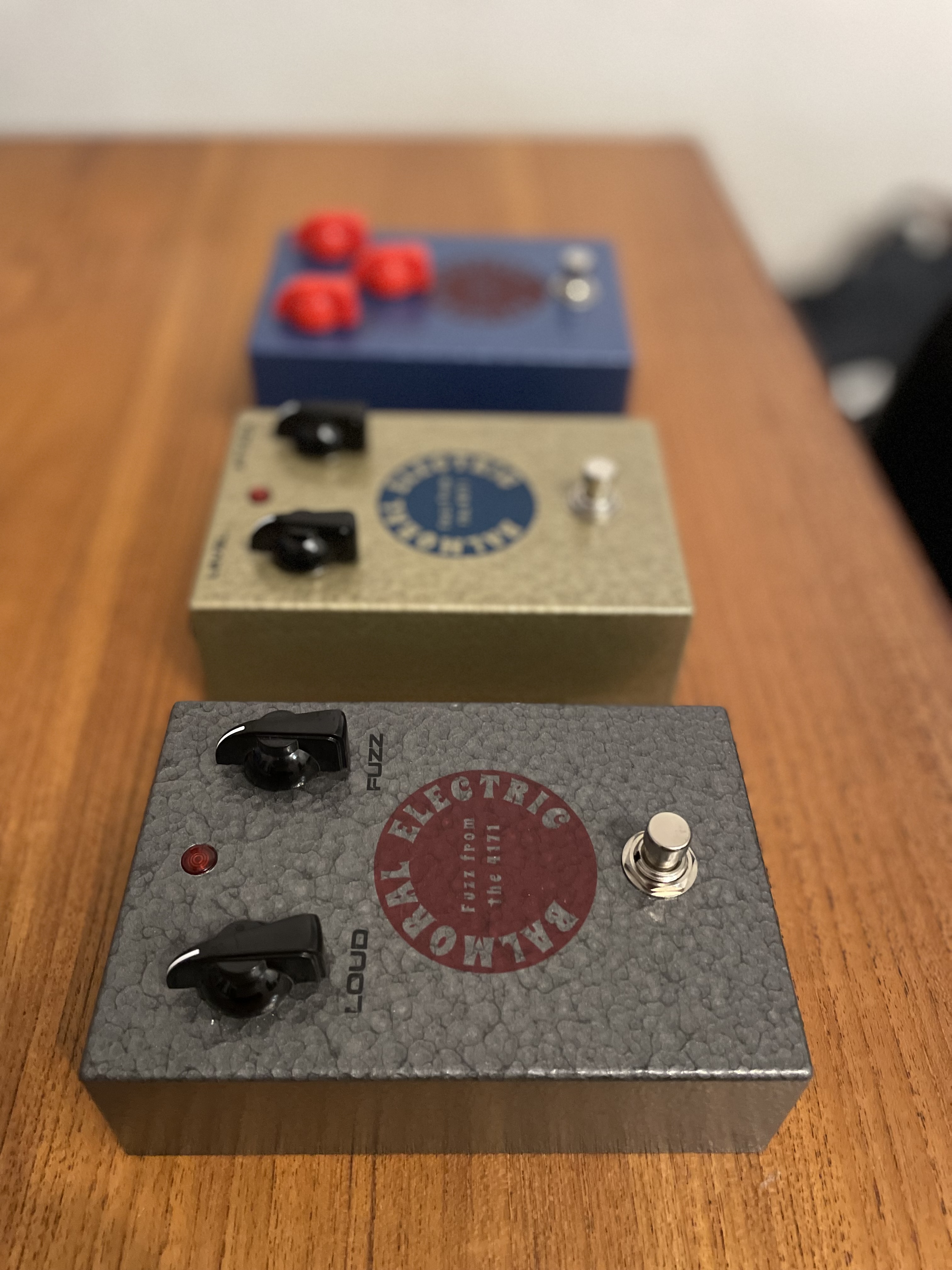
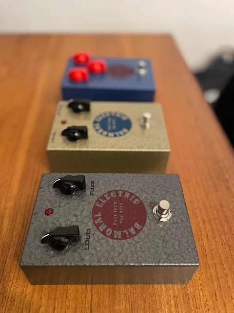
BALMORAL ELECTRIC: Set of Tone Benders (MKI, MKII, MKIII)

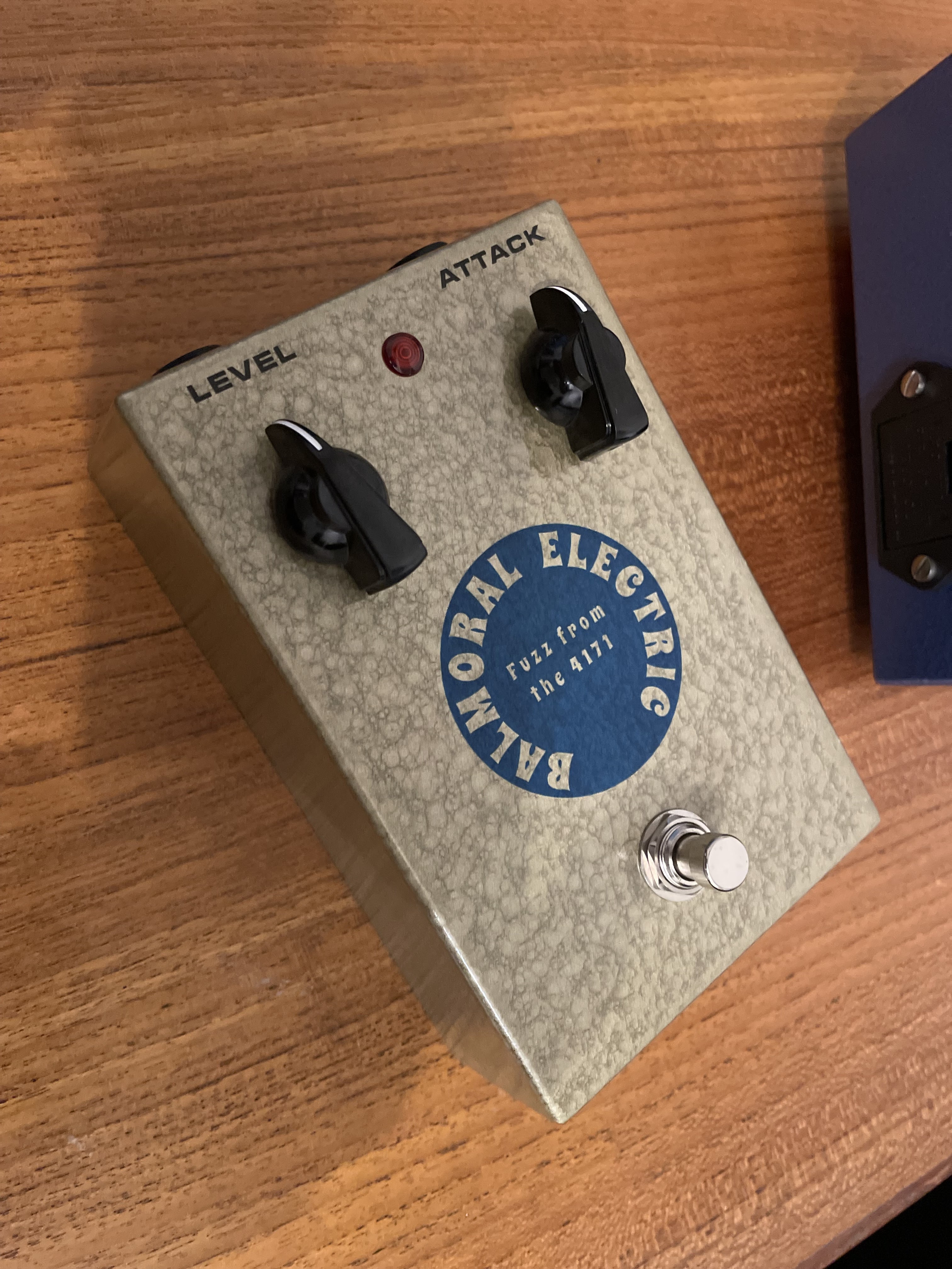
Just to offset the amplifier posts for the pedal folks - here’s a set of three Tone Benders that I just finished.  By a set I mean a MKI, MKII and a MKIII - and no I did not include a MK1.5.    


The layouts and info on how to build these can all be found on the blog.  Standard MKI on phenolic, Sola Sound MKII and the MKIII uses the D*A*M Fuzz Sound layout with stock values.  

Off-board wiring for positive ground with the battery draw and LED can be found here and if you want to get a really fancy, tips on cable lacing can be found here.

Tone benders

The enclosure is a Hammond Eddystone available from RS.  Instructions for how to do a battery cut-out using simple hand tools can be found here 

Tone benders

Tone benders

Tone benders

Tone benders

Tone benders

Tone benders


Saturday, August 5, 2023

COLORSOUND x D*A*M: Fuzz Sound

Following on from the previous post, this is the D*A*M version of the Colorsound Fuzz Sound.  Thread on the D*A*M forum can be found here.   Basically take a D*A*M Fuzz Sound, and change the Fuzz pot to an internal trimmer. 

Unlike the regular Park 2 knob with a large 25u coupling cap between the darlington pair and Q3, D*A*M has stuck with the stock 220n cap.  However, the cap from the emitter of the darlington pair to ground has been increased, which provides a bit of a bass boost.  There's also the bigger caps in the filter section, often used by Dave Main, which is also my favourite set-up.  It just drops the cut-off of the high pass filter on the treble side down and helps with the bass response.   It also has a smaller resistor between the tone and volume pot.  

So despite the smaller coupling cap, this has been accounted for elsewhere.

COLORSOUND x D*A*M FUZZ SOUND -  0.15" VERO LAYOUT


COLORSOUND x D*A*M FUZZ SOUND. -  GUITAR EFFECT FUZZ 0.15" VERO LAYOUT


Thursday, August 3, 2023

PARK: Fuzz Sound, Two Knob Version, tag board layout

Request for Phil - one tag board layout for the Park 2 knob fuzz sound.   I generally prefer to keep the links below the board, as it looks neater.  I don't mind linking two adjacent lugs on top, as you hardly notice it.

One suggestion for this.   The D*A*M Colosround Fuzz Sound has a few different values and an internal trimmer to fine-tune the fuzz.   They say that it's set at about 90% - so given that the pot is normally 100k, you could use a 10k resistor instead of a link under the board, or any value resistor of your choice. 

Check the MKIII component values table as a reference.  Stock values are listed below.

PARK TWO KNOB FUZZ - TAGBOARD LAYOUT

PARK TWO KNOB FUZZZ TAGBOARD LAYOUT


Friday, December 9, 2022

BUZZAROUND: Component Values Table

GENERIC BUZZAROUND SCHEMATIC


BUZZAROUND COMPONENT VALUES TABLE


Wednesday, December 7, 2022

TONE BENDER MKIII: Component Values Table

This isn’t a complete reference of every Tone Bender MKIII / MKIV ever made. It’s a working table compiled from multiple online sources and gut shots, so treat it as a guide rather than absolute gospel.

In some cases, it's difficult to have a definitive set of values for any one pedal, as they are known to change over time, with different production runs.

Where values are unknown or unsure, you'll see a question mark in the table.

GENERIC MKIII / MKIV TONE BENDER SCHEMATIC

Common components have been left as is, and I know the 100uf cap varies, but it makes no difference really so I didn't see the point of listing every variation.  Arguably, there's also no difference between a 220pf and a 200pf cap either, but I put that in any way. 

GENERIC MKIII / MKIV SCHEMATIC


I've added the board below as a reference, as most MKIII boards look like this.  I "borrowed" the image from a Antique Electronics file - they have some great products available, including this board.

So if you're looking at a gut shot online and are not quite sure what's what, this might be helpful.  A few key things to look for.
  1. Bias resistors R1 & R2 on the base of Q1.  These are conveniently marked with asterisks below - they frequently vary.
  2. The capacitor C3 on the emitter of Q3.  This effects the bass response.   
  3. The treble and bass caps - these are nearly always tweaked on D*A*M builds (which I quite like and frequently use)
The rest rarely change, or the changes are relatively minor in terms of sound.   D*A*M does use a 470k volume pot and omits the resistor R4 between tone and volume controls.  This is primarily a way to boost the output without really changing the tone.


EFFECT OF C3 ON BASS RESPONSE

C3 on the schematic tables above - Darlington pair emitter capacitor 

TONE BENDER MKIII / MKIV ON LTSPICE


C3 on the schematic tables above - same again but response taken at the output


R1 / R2 BIAS RESISTORS

Comparison of different bias resistors on the darlington pair, taken from the 220n cap

This compares 220k/47k,  680k/100k & 1M/100k


Comparison of different bias resistors on the darlington pair

Apart from the output level, the resulting wave is a little different for each one, and of course 100n/47k vs 100n/100k form different high pass filters, resulting in a slight difference in low end.  This can be further tailored with the value of C3 (the capacitor on the emitter of Q2).

So despite some people referring to it as just a boost stage, and that it doesn't matter that much - choices here do matter. 

Higher bias resistors result in more gated sound, lower bias resistors provide a smoother sound - at least in my experience anyway.   Different transistors in the darlington pair will come into play here as well, depending on how the bias etc - higher gain sets hit Q3 harder.


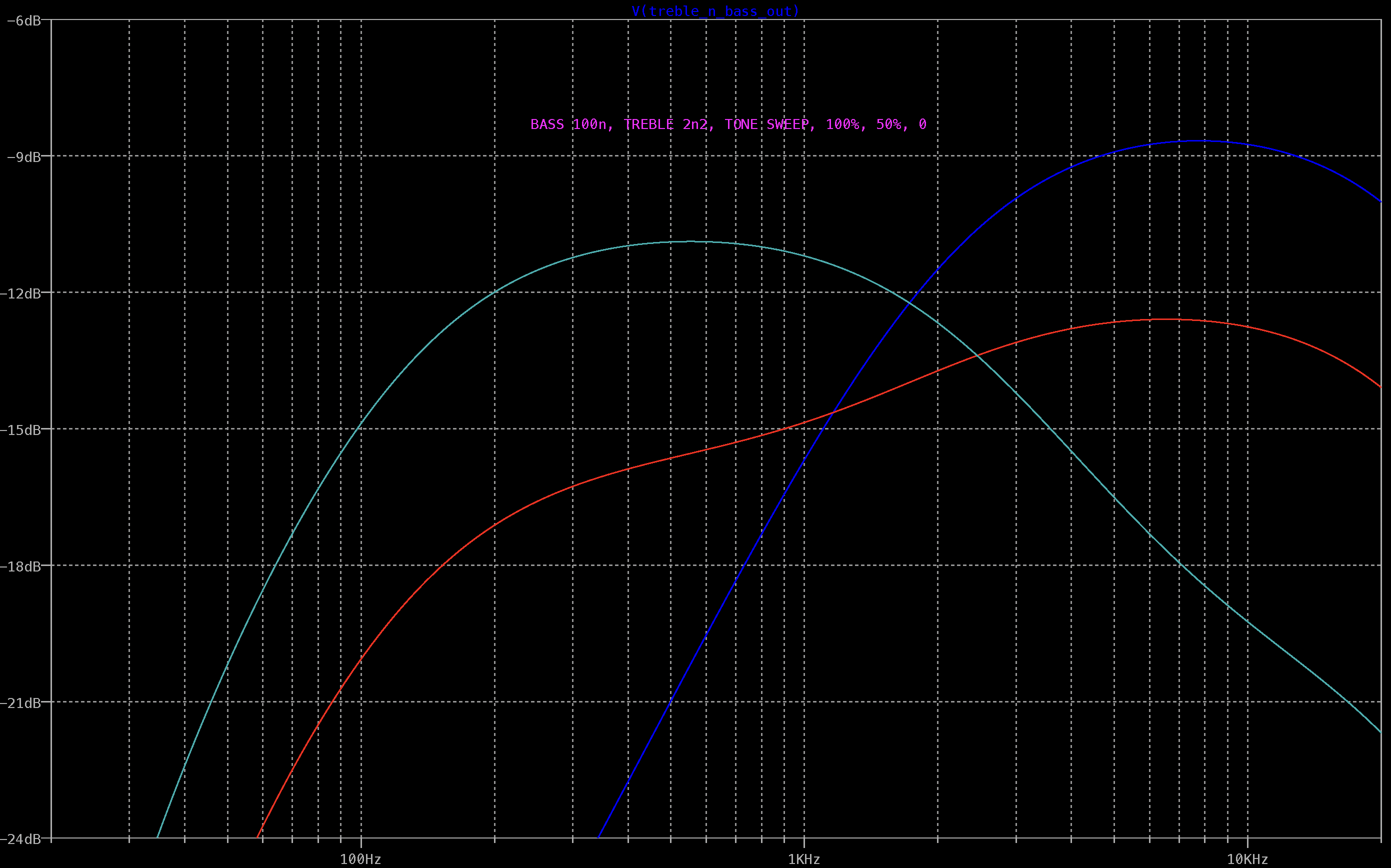
MKIII TREBLE N BASS VALUES

A lot of the character of the pedal comes from the filter section.   I think it's fair to say that apart from the fuzz itself, this is the most important tone shaping section of the circuit.

Below are the frequency responses of some of the more common values found, with the tone pot in the centre position and swept to either side.  Increasing C5 lowers the high-pass filter / corssover point of the treble and bass, bringing more high-mids into the mix.  A side effect of this is that the treble side also gets louder, which can be balanced by the bass side to some degree, but it might also be worth increasing C3 to offset the change.




Sunday, April 24, 2022

D*A*M: Fuzz Sounds FS-77

A full description can be found here, which is the tagboard layout.  I built mine on tagboard, but that isn't for everyone, so the standard vero layout is below.


D*A*M FUZZ SOUND FS-77 - VERO LAYOUT

D*A*M FUZZ SOUND FS-77 - VERO LAYOUT


Sunday, February 13, 2022

PARK: Fuzz Sound

Another Tone Bender MKIII / MKIV variant - is the Park Fuzz Sound.  I'd already done a P2P layout, so I thought I should also do a standard vero layout.  As maybe one other person and I have used the P2P layout...   

I guess the most obvious difference is the lack of Fuzz pot - apart from that, it has a larger coupling cap between the two stages, and that's about it really.  


PARK FUZZ SOUND - VERO LAYOUT

PARK FUZZ SOUND - VERO LAYOUT


Sunday, January 30, 2022

BALMORAL ELECTRIC: MKIII / MKIV Tone Benders

Two new MKIII / MKIV Tone Benders finished over the weekend - the circuits have been finished for a while, just had not got around to boxing them up.  Hopefully off to new homes shortly.   Pity Gapco is now out of stock with these enclosures - I should have bought more when I had the chance…

One has a traditional MKIV spec, and the other is more like a D*A*M Fuzzsound / MKIII.  


MKIII / MKIV Tone Benders

MKIII / MKIV Tone Benders


As a comparison - the main difference between the two is that the D*A*M uses different filter values (tone stack).  A 220n and a 4n7 cap for D*A*M vs 100n and 2n2 in the stock Sola Sound (3.3khz vs 7.2khz).  Basically, the D*A*M has more prominent mids, as the high pass filter on the treble side has a lower cutoff.  Of course, there's a lot of talk about what transistors are used and the impact that has on sound - which I think is more of a textural thing, but I won't go down this road.


tone bender MKIV vs dam fuzz sound freq response


The difference with the bias resistors on the base of Q1 also makes a small difference in the frequency response, but nothing significant by the time they reach Q3. D*A*M uses 220k / 47k, which is used in the Sola Sound MKIII Tone Benders, whereas the MKIV uses 680k / 100k.  Check out the tone bender values tables post if you’re interested.

tone bender mkiv vs dam fuzz sound darlington pair freq response


Tuesday, March 2, 2021

Tone Bender MKIII, Q3 Transistor Comparison (OC71, OC75, OC81)

Now I didn't go as far as measuring and matching gain and leakage (as much as possible), but here's a comparison of a few Q3 transistors for a Tone Bender MKIII - all the same setting, just swapping Q3 on the breadboard.

Why?   I saw someone on Facebook poking fun at an eBay seller in Thailand over what they thought were fake OC71.  I bought some as the seller looked legit to me, as did the transistors -  so I tested them yesterday, and it turns out they are real, so I promptly ordered more.

Lines on a screen don't replace ears, but as you can see, they are quite similar.  There are definite differences in harmonic content, with the 2nd and 4th being the most obvious.  On the scope, the waveforms are very similar, with hard-to-pick differences.

I could talk about the sound, but it's very subjective... 


Unbranded OC71


Valvo OC75


Mullard OC81


Saturday, February 27, 2021

ELKA: Dizzy Tone, 0.15" Vero Layout

The Buzzaround's Italian cousin - the Elka Dizzy Tone.  Extremely similar, some are seen with a 1M Attack pot.  This layout is based on the D*A*M Fuzz Sound MKIII layout.  


ELKA DIZZY TONE   -   0.15" VERO LAYOUT

ELKA DIZZY TONE - 0.15" GUITAR EFFECT VERO LAYOUT


VIDEO DEMO


Wednesday, February 24, 2021

Tone Bender MKIII, 100k fuzz pot vs 250k

This is in response to a question I saw that asked on Facebook regarding reducing the minimum amount of fuzz available on a Tone Bender MKIII / MKIV.

With the fuzz pot at full, there's almost no resistance between the first stage and Q3.  The fuzz pot acts as a variable resistor, so even at the lowest fuzz setting (highest resistance), the signal still makes it through to Q3.  In the case of a stock Tone Bender, this is 100k.   So increasing the resistance reduces the amount of signal reaching Q3, meaning less fuzz.

TONE BENDER MKIII FUZZ POT VALUE COMPARISION

100k fuzz pot - the lowest setting

Total harmonic distortion - 39%

Level is -16.9dB


250k fuzz pot - the lowest setting

Total harmonic distortion - 28%

The level is -18.7dB  (close to 2dB lower)

It's easy to see a lot less in terms of harmonic content in the spectrum analyser window compared to the 100k pot - less fuzz.


There's definitely less gain using a larger pot, if you would like a bit more range on the fuzz.  Sometimes the lowest setting can still be pretty intense on a stock MKIII / MKIV.  

Dropping back the 10k resistor to 4k7 on the collectors of Q1 & Q2 also helps, but not as much as the pot.   You get slightly less clipping from the first stage this way.  

Saturday, February 13, 2021

OFF-BOARD WIRING: Tone Bender MKIII

Off-board wiring for any Tone Bender MKIII or MKIV - this is just how I do it; it's not exactly vintage correct.  

The cable with a grey offshoot is shielded.  Note where shields are not connected. I've grounded the enclosure via a pot; this is only sometimes necessary or recommended, depending on the style of jack used (insulated plastic vs open metal).  

It might also be advisable to create a dedicated ground connection to the enclosure instead of using a pot. It's the better way to go in most cases. I've only done it because I didn't want to drill another hole in the vintage-style tone bender enclosures I've been using lately. 

One thing that I did recently was to use uninsulated wire to run through as many ground points as possible before soldering.  I think it looks neater and is easier than daisy-chaining individual cables.

TONE BENDER MKIII OFF-BOARD WIRING LAYOUT

TONE BENDER MKIII OFF-BOARD WIRING


side note:  I stopped using this size cable, as it was too heavy to work with.


Same again but with the jacks reversed, and the wiring is not insulated, which is mostly how I'm wiring them up these days.


Saturday, January 23, 2021

BALDWIN-BURNS: Buzzaround Timbre Mod, Schematic

A simple mod to provide more flexibility for the timbre range of the Buzzaround.

One side of the timbre control is 15khz high-pass filter, which is very high.  The useful range of the timbre sweep is rather limited as a result of this, and there's also a bit of volume loss that comes with this.

Some D*A*M Buzzotrons have a 33k resistor instead of 10k, which sets the filter at 4.5khz, providing a more usable range, but it's tonally different to the original.   

Adding a trimmer or a pot, allows flexibility setting the HPF without much effort.


SCHEMATIC - BUZZAROUND TIMBRE MOD

SCHEMATIC - BUZZAROUND TIMBRE MOD FOR GUITAR EFFECTS


Thursday, December 31, 2020

Wednesday, December 30, 2020

BALDWIN-BURNS: Buzzaround, Tag Board Layout

This is my slightly more spacious take on the original tagboard layout for the Baldwin-Burns Buzzaround.   Same size board and the same layout; it's just spread out a bit more to take advantage of all the lugs available.  


BALDWIN-BURNS BUZZAROUND - TAGBOARD LAYOUT

BALDWIN-BURNS BUZZAROUND - TAG BOARD LAYOUT


Wednesday, December 9, 2020

D*A*M: Buzzotron, Schematic

 D*A*M BUZZOTRON - EARLIER VERSION SCHEMATIC

D*A*M BUZZOTRON - EARLIER VERSION SCHEMATIC


D*A*M BUZZOTRON - LATER VERSION SCHEMATIC

27k instead of 22k resistor to Balance pot and 33k instead of 10K resistor from 1n on the Attack control to ground (lowering the filter frequency)

D*A*M BUZZOTRON - LATER VERSION SCHEMATIC