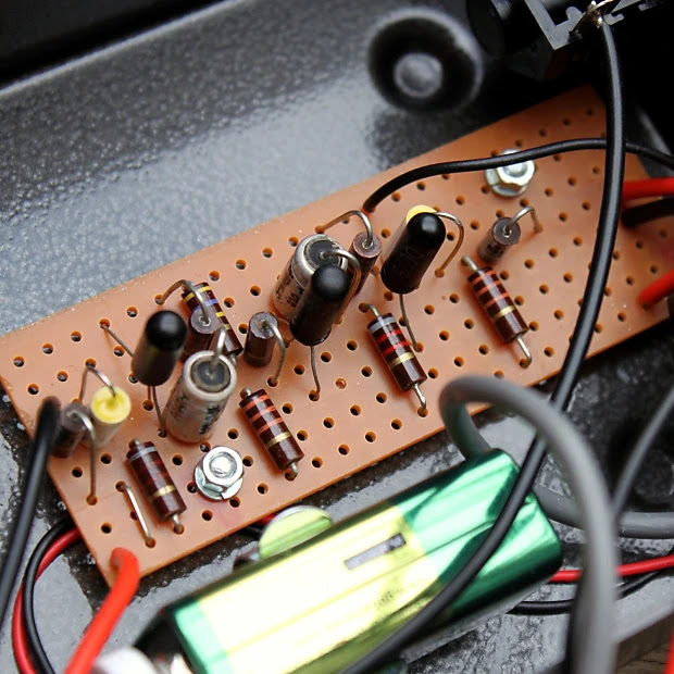
I came across a series of photos of this build on the PedalPCB forum, and there seemed to be a bit of confusion around the schematic. Thought it was worth documenting some of the observed values here for reference.
The board shown below is from the wedge enclosure. There’s also a more pedalboard friendly version, which includes an internal tone control. It looks to be implemented with a trimmer and a capacitor in series at the output of the circuit — not unlike the approach used in a Marshall Supafuzz MKI. I tried a 4n7 in series with a A1M pot on the breadboard - worked just fine. There also appears to be a resistor and a small value capacitor in parallel to ground on the input of the circuit - kind of hard to see that bit, but it looks like 2M and 1300pf.
A few of the capacitor values are non-standard, and there are some variations in the resistor values as well — clearly some biasing tweaks and tuning by ear going on here.
The Zonk / MKI switch is a nice touch. It adds a 2n7 capacitor in series with a 10n capacitor at the input. It’s a clever implementation too - mounting the 2n7 directly on the switch reduces the number of connections back to the board and keeps everything neat and tidy.
They're all impeccably built - amazing work.
CUNNINGHAM AMPS ZONK / MKI
As always with these circuits, while the passive component values are easy enough to document, the real story is in the transistors - their gain, leakage, and how they interact in-circuit. That’s the part you can’t see on a schematic, and it’s what makes or breaks a MKI style circuit.
Yes, it's another MKI. I designed this layout based on a Zonk to fit a specific enclosure width. So nothing remarkable, just one for me to use later.
MKI TONE BENDER - SHORTY
It's missing the 33k resistor that normally sits across the 50k pot, cause I like to use an A25k instead. I sometimes make a few other taste related changes, depending on the transistors, etc.
I’m surprised I had not covered this one before, but I suppose it is a MKI, so it should feel fairly familiar.
There seem to have been a few different iterations — essentially just different flavours of the MKI, so keep that in mind when choosing transistors and biasing the circuit. Some versions also used the more familiar point-to-point MKI style board.
Basically it cuts the output limiting resistor in half, from the stock 2.2 Meg down to 1 Meg. The first batch of the new 2015 1965's that went to Joe all had approx 1.5 Meg limiting as stock and the Super Zee bypassed it entirely.
Also worth noting from another post: What no side switch? This is correct. It was making my tuning of the pedal a little erratic at times.
I have not listed transistor types, because they varied, and the chances of you having the exact same transistors D*A*M used — and for them to sound great in a MKI anyway are fairly small. Even from reading posts on the D*A*M forum, Dave appears to have moved away from using 2 x OC75s in this circuit because they were less stable than other options - and you can be pretty sure that D*A*M has a larger selection of transistors to choose from than you or I.
So this looks like one of the D*A*M one-offs from back in the day - a MKI style fuzz, using a variation on a Zonk layout. There are some departures from stock values, some of which are not entirely clear.
There are a few components that are not visible, but if you have any build experience, you can make some reasonable assumptions. Pop it on a breadboard... I know that's what I'm about to do.
One thing that throws me is this - the resistor next to the OC45 (the Q2 collector), is it brown green red gold, (1k5) or purple green red gold (7k5)? I think 7k5, the schematic on FSB says 1k5.
On the breadboard, 7k5 works just fine, so I'll stick with what I see and hear. Can't always trust what you find online, including here ;-)
Quick Zonk Machine layout to suit an enclosure that I just picked up from MW Pedal Parts - pretty much one row difference in terms of where the mounting holes are drilled compared to old layout that I have been using, and I decided to move a couple of components around while I was at it.
MW are great by the way - no hesitation in recommending them based on my experience. The ordering process is a little unusual, but they deliver on the goods.
I've had a couple of questions about these recently, and out of curiosity I decided to take a closer look. In 2024, Sola Sound released a few versions of a hybrid MKI, built by Dave Main of D*A*M.
So what is it? It’s essentially a standard MKI circuit, but with the first two germanium transistors replaced by silicon transistors. Because silicon devices don’t leak like germanium, a few extra resistors are needed to get things working properly.
As this is an incomplete trace and there are circuit variants - use the info below as a guide only.
That being said, I have breadboarded this with success - transistors matter.... It sounded a lot like the video demo below, and it was easy to tune playing with input and coupling capacitor values.
SOLA SOUND HYBRID MKI LAYOUT
There aren’t many photos available - I couldn't make out a few values, but I got most of it. You’ll want to experiment on a breadboard and dial things in before committing to solder.
I ended up making a slightly different layout, as I didn't like some of the placment on this one.
The two values that I just could not see anywhere: R3 & R7. For R7, start large and scale down, it seems to tame the gain somewhat - it can also assist with noise if this is a problem. For R3 I tried a couple of different values. I have 4k7 on the breadboard at the moment.
The cap values that I could not really see are C1 & C2 on the input & C3. C3 is just a suitable large electrolytic cap, normally a 22u.
I’m currently using 8k2 for R5 with a 50k pot. Could probably use a 25k pot and skip R6.
Groke
Note that R9 is actually 2 x 15k resistor in parallel, wich may as well be the stock value of 8k2.
The Griffin
Some difference with R5 & R6 are visible.
Brandy Snap
Looks like a 15n input cap with a 4n7 to ground. 1u coupling cap. Maybe a 1m5 resistor on the output.
Just to offset the amplifier posts for the pedal folks - here’s a set of three Tone Benders that I just finished. By a set I mean a MKI, MKII and a MKIII - and no I did not include a MK1.5.
The SonicVI silicon MKI Tone Bender is firmly based on the original, with a few additions and some minor changes.
Being silicon based, the transistors do not self-bias, so additional resistors have been added from V- to the base of Q1 & Q3.
The transistors used are early Mullard PNP silicon OC202 which are quite low-gain and still available at reasonable prices. In terms of gain, it's down in the 40-120hfe range.
I tested some random vintage silicon transistors that I had handy, and around 85hfe did the job. Being silicon, this is easily flipped to NPN by reversing the electrolytic caps, as long as you have similar transistors. I've tested with PN2222A and it was fine. Out of the transistors tested, the lower gain vintage ones sounded a tad better to my ears - I suspect this has more to do with hfe than age.
ASSUMPTIONS
Given I did the layout based on a photo from Reverb, there are some unknowns - not too many though, as most of the values are clearly visible.
Trimmer: A 25k to 50k trimmer works well, set on the edge of gating to get that MKI decay.
Attack: The Attack pot is paired with a 150k resistor - 50k is fine, quite possibly with a low value resistor hidden under the board. Tune it so it just cuts off with the pot on zero. I'd say test this with a couple of different size pots (50k or smaller), to see what suits you.
Level: I've assumed the value of the Level pot to is 500k, which is the same as a MKI
SONIC VI SILICON MKI TONE BENDER - EYELET BOARD LAYOUT
I added the 100uf that's seen off-board in the photo to the layout, as it's just a bit easier to attach here, vs the DC jack.
photo care of Reverb listing
MULLARD OC202 DATASHEET
SONIC VI SILICON MKI vs PIGDOG MKI
STANDARD VERO VERSION - NPN
I guess not many people will be interested in the eyelet version, as cool as it may look - and this is NPN that will fit in a 1590B enclosure.
version 1a - error corrected on v1.
BREADBOARD TESTING - WORK IN PROGRESS
It’s sounding really nice on the breadboard. Sharp attack, same frequency response as a stock MKI, and there’s even the spitty decay on the end of notes.
It did pickup radio on the breadboard and squelch a bit - a low value cap on the input sorts this out. Not sure what I even have on there at the moment as I picked up a random small greenie off the bench - think it's 3n3. Needs a cap on the power supply, again, helps with noise.
Tested with;
2N4036 PNP Silicon (vintage ones, although they were in production until quite recently)
Someone mentioned this in the comments recently (thank you ClassicFuzz), so I thought I'd have a look at the photos on Reverb.
The Goldie is a MKI in a MKII enclosure from March 2022, likely to be inspired by this unit found in Germany - which is an absolute train wreck of work.
It looks a lot like a MKII board, it even has a cap to ground on the input - a full set of OC82 transistors is also more likely to be seen on a MKII. That’s about where the differences end - a nice nod to a MKII, but it’s definitely a MKI.
This Goldie should not be confused with the other Goldie, which is a MK1.5 - confusing no?
SOLA SOUND / D*A*M GOLDIE MKI TONE BENDER - 0.15" VERO LAYOUT
Apart from construction, the most obvious difference to a regular MKI is the cap to ground on the base of Q1 (the silver polystyrene cap). I haven't been able to spot the value anywhere - thought I could vaguely see an n3 on one, meaning that it might be a 3n3 or similar low-value cap. D*A*M have used a 3n3 on the input of some MKIs in the past, so probably a safe bet that this is the same.
I also haven't put eyes on the value of the brown box cap, which is most likely 100n (standard value). Same for the input cap, I'm assuming 10n as a standard value, but you never know.
Below is the version with the extra resistor in parallel with the 470k which would change the biasing of Q2. It also appears to have a 47k resistor instead of a 56k resistor on the output. 47k vs 56k makes very little difference. A slight change to the HPF that it forms with the 100n cap, but not much to worry about (34hz vs 28hz respectively). There's probably a similar range of variance just with normal component tolerances.
I purchased a sheet of phenolic board locally to make some MKI boards, as I didn't want to pay $25 postage on a $3 board from the USA (postage to Australia is often a killer). I couldn't find a template anywhere, so I reversed one from a product image online - I did make one slight change to the online product, as I didn't like the alignment of the resistors and capacitor on the righthand side.
I think it's pretty close as a MKI template, even if it's a metric approximation. I've built a few boards using this, and the spacing does work with 1/2 watt carbon composite resistors.
MKI TONE BENDER - PHENOLIC BOARD DIMENSIONS / TEMPLATE
safety message: wear breathing protection when cutting board, even if it's just a medical mask.
Just a reference for me - this is specifically for this layout mounted above the pots.
MKI TONE BENDER OFF-BOARD WIRING PLAN
The final soldering of the board to the pots has not been done yet - that will be done when it is mounted on the actual enclosure lid, as opposed to the dodgy piece of cardboard that I'm using as a wiring template.
These little clips are handy for securing the reasonably heavy Belden shielded cable I'm using. It has its own ideas about how it would like to bend. I could probably warm it up and reshape it, but I don't mind. It's normally a two-core cable with shield, but I remove one core and use it for other purposes.
If you're wondering, transistors: Q1, OC71. Q2, OC44. Q3 NEC ST303 (later removed and replaced with an OC71)
The Sounds of Today is Ian Sherwood from Ghost Effects adaptation of the MKI Tone Bender. It's all explained by Ian here, with photos. There are also plenty of photos of these in various stages of construction Instagram too, so you can see a few variations along the way.
Short story: The attack has been replaced with a fixed resistor. The resistor in Q2 collector is now a bias pot, and the drive pot restricts the level into Q3.
GHOST EFFECTS SOUNDS OF TODAY - TAGBOARD LAYOUT
As you can see, there are a few unknown values - and if you build this kind of thing, I'm sure you will be confident enough to try a few things and work out what you prefer. It is an MKI after all, and these often take some tweaking/transistor tests to get sounding good.
In my experience, the Zonk can be a little easier to make than the MKI in terms of transistor selection, and just getting a sound out of it - but it's still not one to rush into without a good stock of transistors to test. If it sounds thin and nasty, it ain't right yet.
Transistors
Q1 needs leakage to work. Q2 doesn't need leakage to work, but it uses an OC75, which are usually quite leaky compared to other transistors. Q3 should also need leakage to work, but it has an OC44 here, which are generally quite low in terms of leakage - this is partly where the gated sound comes from.
A good way to test Q1 is to play through it on the breadboard. Just take the output directly from the 22u cap (disconnect the next stage) and see how it sounds. It should sound clean and sustain. Listen for noise. Any noise here is just going to get a lot louder.
For Q2 I like to bias it so when the fuzz is turned all the way down, it’s either not working at all, or barely working. Then the pot will have some range.
Dave Main of D*A*M fame was kind enough to share some voltages and transistor hfe on a schematic, which is as follows.
Q1 Texas Instruments AO2650 hfe 30
Q2 Mullard OC75 hfe 156
Q3 Mullard OC44 hfe 69
Voltage on Q2 collector
-5.1v on full fuzz
-9.6v at zero
Most batteries start life at 9.5v so I have no idea what kind of freak battery Dave had plugged in to get -9.6 volts. Anyways, it will be a high voltage in any case, a range of -5 to -7v would be pretty normal.
And here's another set of quite different readings from an original Zonk, care of acidfuzz on freestompboxes. Great to see some leakage measurements as well.
and here's a demo, of what might be the very same pedal, as the video is provided by acidfuzz.
Input capacitor
The 1nf input capacitor is really the standout component value on a Zonk - this is really what sets it apart from the MKI Tone Bender. In the video demo above, the Zonk sounds quite fat - it's not easy getting this tone. I've found that a higher hfe Q1 helps and in some cases a lower gain Q2. This is not a hard and fast rule by any means.
If your Zonk is sounding a bit thin and nasty, it's not the end of the world if you increase the size of the input cap until you get it to a place that you're happy with. Try a 3n3. There's a lot of builders out there that offer this circuit with a MKI switch, which basically swaps or adds another input cap to increase the value to something like a MKI (10nf).
The sizzle
The what now? Zonks sometimes have an annoying sizzle on the decay, some people say it sounds like bacon cooking, and you don't really want that - or maybe some of you do? Some sizzle is not unusual on the decay of a MKI style circuit, but the Zonk can have way too much at times.
First, try different transistors - I've found lower hFE on Q2 to be helpful. If you can't fix sizzle with transistor swaps, try a low value cap directly on the input of the circuit. You want something big enough to reduce the sizzle down to manageable levels, but not so big that it changes the tone too much, although this can sound kind of cool, it's a bit like a cocked wah sound if you go too big. A 1nf cap often does the trick without affecting the sound.
Like most people, I've never even seen an original MKI in the flesh, so I'm relying on online references for this. The references below all relate to original MKIs - or pedals that are said to be direct replicas of originals built for Sola Sound.
Please feel free to comment and point me in the right direction if you think there's something I should correct or add - ideally with a link to a reference somewhere. Unfortunately, there are only a handful of MKIs left in existence, so new reference material is difficult to come by.
GENERIC MKI TONE BENDER SCHEMATIC
This is the basic schematic for all MKI Tone Benders, with or without R5 & R11and C3 is sometimes electrolytic. Yes, I know the pots were 47k and 470k, but hey...
I'm certain that anyone who has found their way to my blog has seen the Dave Main schematics, the gospel for Tone Benders. As it happens, there seem to be some other values floating around out there from original MKIs that are not well documented - hence this post.
Apart from a number of small variations that are to be found, I believe that there are three basic types of MKI circuits that roughly match different production periods - for want of better names and to match the existing schematics out there, they are the;
Wooden box
Gary Hurst
Sola Sounds
There are variations even across these three - despite the variations, they can still be grouped together largely based on capacitor values and production methods.
The Wooden Box
The wooden box is the earliest of all Tone Benders - and of course very few still exist. This is what I think sets them apart from others;
Constructed on vero board & gooped
3 x OC transistors - exact type unknown, thought to be OC75 or similar
22n input cap, 22n output cap and 2 x 25u coupling caps
33k resistor across Attack pot
The wooden box circuit is the basis for a lot of Stu Castledine's MKIs, as he happens to own one that was rehoused in a metal enclosure at some stage. The information above is based entirely on Stu's MKI builds - there are some minor variations between builds, so take this as general guidance only.
The 22n input cap and the two 25u coupling caps let a lot of additional low-end signal through at the start of the chain, which is then reduced by the smaller output cap.
The last of the line - this is when Sola Sounds appears on the front of the metal enclosure. Very similar to the previous, but with a few changes to biasing and coupling caps.
Point to point on phenolic board
1 x Mullard OC75 & 2 x Texas Instruments 2G381 transistors
All MKI Tone Benders have a 10n input cap right? Apparently not. Stu Castledine's very early version has 22n input and output caps. Dave Main's Phoenix has a 68n input cap and more recently, one has appeared with a 4uf cap - did it leave Macari's like this, who knows? The MKI based Marshall Supafuzz also used a large input cap, so maybe...
These changes both make a significant difference to the sound, as more low-end is making to Q2, which is where a lot of the magic happens.
C3 - COUPLING CAP TO Q3
Values spotted: 50n, 100n, 25u & 40u
HPF
40u 8k2 = 0hz
25u 8k2 = 1hz
100n 8k2 = 194hz
50n 8k2 = 388hz (maybe)
NOTE: This is just the RC filter calculation - when a leaky transistor is added, these values will increase by varying degrees. Check out the detailed calculations here
It's the change from a large electrolytic cap to a 100n cap that really makes a difference. The higher cut-off of the HPF before that last transistor has a noticeable effect on the tone.
C4 / R10 - OUTPUT CAP / HPF
C4 and R10 form yet another HPF - most MKIs have 100n here, with either a 47k or 56k resistor for R10.
HPF
100n 56k = 28hz
100n 47k = 34hz
47n 56k = 60hz
22n 47k = 154hz
22n 33k = 219hz
The 22n output caps are only found on the wooden box version, which is paired with larger input and coupling caps - the HPF is removing some excess bass. It does not sound thinner by any measure.
TUNING NOTES:
These are my notes from breadboarding and spending time testing a lot of transistors + a bit of reading on the internets. Your results may vary. If your MKI is not sounding good, the first place to look is the transistors, and the bias of Q2.
Q1
Just a buffer really - there are minor differences with any transistor that will work in this position. Need some leakage here. OC75s usually leak like sieves.
Q2
Spend time getting Q2 right - it's perhaps the most important transistor in the circuit
Full attack - voltage will drop from close to 9, down to about 5 (in very round figures).
Q3
Affects the general character of the fuzz, including high-frequency content. Lower gain and leakage reduces fizz and scatty note decay (and can act as a noise gate). Despite Q2 doing most of the work, Q3 is still pretty important.
BIAS RESISTOR R3
Anywhere between 180k - 470k have been used. Adjust to taste and your transistor stock.
ATTACK POT
Not unlike the bias resistor - if you have to tune it to taste with R5, there's nothing wrong with that. Smaller bias resistor (R3) can mean smaller pot value. Log pots are recommended by some.
Parallel resistance for the Wooden Box & Gary Hurst versions
50k pot + 33k resistor = approx 20k
The Sola Sounds version does not have the additional resistor across the 50k Attack pot.
Do not expect a nice even sweep of fuzz across the range. It can happen, and it's nice when it does, but sometimes it doesn’t work out like this (log pots often fix this). Note the video below for a demonstration of this, using original Tone Benders.
SYSTEM MKI TUNING TIPS FROM SEEKER ELECTRIC EFFECTS
So nice that this was shared
REFERENCE VIDEO BY GRAHAM GREEN - ORIGINAL TONE BENDERS
ADDITIONAL REFERENCES: RECENT BUILDS FOR MACARI'S (LATE 2022)
I wasn't aware of this version of the MKI until today. I'm sure you have probably seen the new line of Tone Benders that Sola Sound is releasing. I noticed that the Stu Castledine version was on vero, and the rest were all on the more familiar MKI board.
So after a little digging, it turns out this is based on a very early Tone Bender that Stu has - so early in fact that Gary Hurst said that it was rehoused from one of the original wooden enclosures.
Here's a link to a site that Graham Green used to run, talking about the providence of Stu's MKI. The excerpt below, as it is quite a long article. Graham has several original MKIs and is a keen collector and historian of early guitar pedals (British in particular).
Of the wooden ones though that’s very different!! To the best of mine (and Garys) knowledge, (as well as many many contacts with similar interests) this is the last complete original example. A friend Stu has one that has the same board but clearly re-housed in an early prototype metal case (with no battery Hatch – Gary acknowledges that to be the case with that particular pedal)
GARY HUSRT MKI TONE BENDER - CASTLEDINE 0.15" VERO LAYOUT
UPDATE: After taking a close look at the values on a Reverb listing (images below), I've updated the layout and MKI component table. It clearly has 22n input and output caps, which is certainly a detour from the usual 10n in and 100n out.
Despite the relatively small output cap, it still sounds fat. 22n and 33k = ~220hz roll-off as opposed to 100n and 47k coming in at ~34hz. It starts with more bass input care of the 22n and a larger coupling cap on the second stage, so it has less to lose on the output. I tried a 100n and it sounded too woolly in the low-end.
Worth noting that the 100n and 8.2k usually found before Q3 has a roll-off of ~194hz. The larger 25u and 8.2k has a roll-off of less than 1hz. So basically things even out somewhat by the time it reaches the level pot. This does of course lead to a different tone, as all three transistors are receiving more bass in this version.
CASTLEDINE MKI PHOTO CARE OF REVERB
note the 22n input & output caps
I believe the output resistor is 3m3 instead of 2m2 - maybe to trim some level off, as this doesn't have a resistor across the 500k pot.
MKI VIDEO DEMOS
MODDED MKI TONE BENDER LAYOUT
I trimmed the layout down and spaced the components out, as I had a piece of vero this size to use and the one above is a little cramped.