I wasn't aware of this version of the MKI until today. I'm sure you have probably seen the new line of Tone Benders that Sola Sound is releasing. I noticed that the Stu Castledine version was on vero, and the rest were all on the more familiar MKI board.
So after a little digging, it turns out this is based on a very early Tone Bender that Stu has - so early in fact that Gary Hurst said that it was rehoused from one of the original wooden enclosures.
Here's a link to a site that Graham Green used to run, talking about the providence of Stu's MKI. The excerpt below, as it is quite a long article. Graham has several original MKIs and is a keen collector and historian of early guitar pedals (British in particular).
Of the wooden ones though that’s very different!! To the best of mine (and Garys) knowledge, (as well as many many contacts with similar interests) this is the last complete original example. A friend Stu has one that has the same board but clearly re-housed in an early prototype metal case (with no battery Hatch – Gary acknowledges that to be the case with that particular pedal)
GARY HUSRT MKI TONE BENDER - CASTLEDINE 0.15" VERO LAYOUT

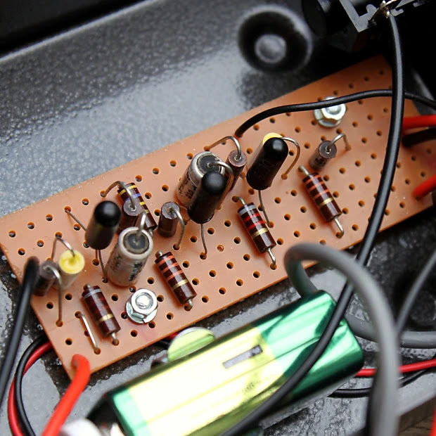
CASTLEDINE MKI PHOTO CARE OF REVERB


MKI VIDEO DEMOS
MODDED MKI TONE BENDER LAYOUT

16 comments:
Just this weekend I build a couple adapting the Zonk Machine original vero layout.
(1 Tone Bender MkI and a mix between a Supa MkI and a MkI with just one knob for the Volume and with an output cap).
For the next one I will try this layout.
Have you ever take a look at the Carlsbro Fuzztone?
https://www.freestompboxes.org/viewtopic.php?t=27766
Cool. Sounds a bit like my weekend.
I haven’t tried the Carlsbro. Thanks for the reference, I’ll give it a try - looks interesting.
I just finished your modded layout. Verified and it sounds amazing. A really really raw and nasty MKI. I love it!
And I just saw your wiring layout. I will try that one too as soon as I get one of the original enclosures. Thank you for all your amazing work! :-)
Great. What transistors did you use?
I’ll probably add some photos to the layout a bit later. I’m mounting the vero above the pots almost the same way that is done with the more well-known poor to point layout. Basically a couple of heavy wires from the board to pin 1 of each pot to float it above the pots.
This time I used GT404, although they often tend to be a bit too leaky.
Something I wanted to ask. What is the gain range of the OC75s?
I only have about ten OC75 left, which are all Valvo pulled from an old Australian telephone exchange (wish I had access to more). They have a pretty broad range - anywhere between 90 - 150 hfe with leakage around 400 - 500 measured on my little multi-function tester. By comparison, my OC71 sit around 60 - 80 hfe with leakage around 400 or a bit lower. In circuit they will work anywhere an OC75 is needed for leakage, but they will be a tad less aggressive sounding due to the lower hfe - this is usually only a minor difference.
The OC75 I have/used are from different manufacturers (Valvo, Mullard, unknown) and they measure usually in the 50 to 200hfe (but I used one with 15hfe that I used as Q2 in a germanium fuzzrite that sounded glorious) and the leakage are all over the place too, from 100ua to 700ua. A bit like OC71 but with more gain usually.
I’ve had the occasional outlier as well - almost very low hfe and insane leakage. One was so bad my tester thought it was a diode - it still worked in a circuit.
Thanks for the update. I'll try the new version asap. I was just wondering, if the 3.3Mohm resistor is necessary or if I could keep the 2.2Mohm resistor. What does this resistor do?
Hello - you can still use 2m2. This resistor helps reduce the output level, as MKIs as extremely loud without it. It makes a difference to the level, but no change in tone.
Thanks! Made the changes (except the 3.3M resistor) and sounds better than before. I like it. :-)
Yep, it’s pretty nice sounding.
Correct me if I am wrong, but I just realised that when I don't build it like Stu and instead mount the pcb to the pots, I have to connect the rows 1 & 2. Otherwise I am getting lots of extra noise bleeding in. I tried this with 4 different versions and they all have less noise and crackling sounds.
Interesting, have not noticed that myself. Will have to try it one day.
I was getting crazy as I thought most of my transistors were noisy. But fortunately that bridge cured it all and now I can use any transistor pair I want without unwanted sizzling :-)
I forgot to mention, I always build mine NPN with an isolated power supply (no battery). Maybe the bridge isn't necessary when building it PNP with a battery.
Post a Comment