Numbers vary slightly by manufacturer and grade, but these headline specs are what give the 741 its “personality” in effects land:
Supply voltage: works on dual or single supplies (it was designed with ± supplies in mind, but can be run single-supply with proper biasing).
Gain-bandwidth product: around ~1 MHz class.
Slew rate: about ~0.5 V/µs typical.
Input bias current: tens of nA typical (bipolar input).
Not rail-to-rail: inputs/outputs can’t swing anywhere near the rails, especially on a 9V battery.
What that means in practice: a 741 can sound/feel a bit rounder and more easily pushed in simple dirt circuits, partly because it’s relatively slow and because it doesn’t have huge clean output swing on a 9V single supply.
LM741 PINOUTS
Note the little tab on the side of the opamp is pin 8.
OFFSET NULL
Offset null is a pair of pins on the 741 that lets you trim out its small DC offset so the output sits where you want it (often 0V on a dual-rail supply).
In pedals it’s usually ignored because stompboxes are typically single-supply with a virtual ground and AC-coupled stages, so capacitors block DC and the tiny offset isn’t audible.
While the pins aren't used, be sure to isolate them anyway.
In my experience, the Zonk can be a little easier to make than the MKI in terms of transistor selection, and just getting a sound out of it - but it's still not one to rush into without a good stock of transistors to test. If it sounds thin and nasty, it ain't right yet.
Transistors
Q1 needs leakage to work. Q2 doesn't need leakage to work, but it uses an OC75, which are usually quite leaky compared to other transistors. Q3 should also need leakage to work, but it has an OC44 here, which are generally quite low in terms of leakage - this is partly where the gated sound comes from.
A good way to test Q1 is to play through it on the breadboard. Just take the output directly from the 22u cap (disconnect the next stage) and see how it sounds. It should sound clean and sustain. Listen for noise. Any noise here is just going to get a lot louder.
For Q2 I like to bias it so when the fuzz is turned all the way down, it’s either not working at all, or barely working. Then the pot will have some range.
Dave Main of D*A*M fame was kind enough to share some voltages and transistor hfe on a schematic, which is as follows.
Q1 Texas Instruments AO2650 hfe 30
Q2 Mullard OC75 hfe 156
Q3 Mullard OC44 hfe 69
Voltage on Q2 collector
-5.1v on full fuzz
-9.6v at zero
Most batteries start life at 9.5v so I have no idea what kind of freak battery Dave had plugged in to get -9.6 volts. Anyways, it will be a high voltage in any case, a range of -5 to -7v would be pretty normal.
And here's another set of quite different readings from an original Zonk, care of acidfuzz on freestompboxes. Great to see some leakage measurements as well.
and here's a demo, of what might be the very same pedal, as the video is provided by acidfuzz.
Input capacitor
The 1nf input capacitor is really the standout component value on a Zonk - this is really what sets it apart from the MKI Tone Bender. In the video demo above, the Zonk sounds quite fat - it's not easy getting this tone. I've found that a higher hfe Q1 helps and in some cases a lower gain Q2. This is not a hard and fast rule by any means.
If your Zonk is sounding a bit thin and nasty, it's not the end of the world if you increase the size of the input cap until you get it to a place that you're happy with. Try a 3n3. There's a lot of builders out there that offer this circuit with a MKI switch, which basically swaps or adds another input cap to increase the value to something like a MKI (10nf).
The sizzle
The what now? Zonks sometimes have an annoying sizzle on the decay, some people say it sounds like bacon cooking, and you don't really want that - or maybe some of you do? Some sizzle is not unusual on the decay of a MKI style circuit, but the Zonk can have way too much at times.
First, try different transistors - I've found lower hFE on Q2 to be helpful. If you can't fix sizzle with transistor swaps, try a low value cap directly on the input of the circuit. You want something big enough to reduce the sizzle down to manageable levels, but not so big that it changes the tone too much, although this can sound kind of cool, it's a bit like a cocked wah sound if you go too big. A 1nf cap often does the trick without affecting the sound.
This isn’t a complete reference of every Tone Bender MKIII / MKIV ever made. It’s a working table compiled from multiple online sources and gut shots, so treat it as a guide rather than absolute gospel.
In some cases, it's difficult to have a definitive set of values for any one pedal, as they are known to change over time, with different production runs.
Where values are unknown or unsure, you'll see a question mark in the table.
GENERIC MKIII / MKIV TONE BENDER SCHEMATIC
Common components have been left as is, and I know the 100uf cap varies, but it makes no difference really so I didn't see the point of listing every variation. Arguably, there's also no difference between a 220pf and a 200pf cap either, but I put that in any way.
I've added the board below as a reference, as most MKIII boards look like this. I "borrowed" the image from a Antique Electronics file - they have some great products available, including this board.
So if you're looking at a gut shot online and are not quite sure what's what, this might be helpful. A few key things to look for.
Bias resistors R1 & R2 on the base of Q1. These are conveniently marked with asterisks below - they frequently vary.
The capacitor C3 on the emitter of Q3. This effects the bass response.
The treble and bass caps - these are nearly always tweaked on D*A*M builds (which I quite like and frequently use)
The rest rarely change, or the changes are relatively minor in terms of sound. D*A*M does use a 470k volume pot and omits the resistor R4 between tone and volume controls. This is primarily a way to boost the output without really changing the tone.
EFFECT OF C3 ON BASS RESPONSE
C3 on the schematic tables above - Darlington pair emitter capacitor
C3 on the schematic tables above - same again but response taken at the output
R1 / R2 BIAS RESISTORS
Comparison of different bias resistors on the darlington pair, taken from the 220n cap
This compares 220k/47k, 680k/100k & 1M/100k
Apart from the output level, the resulting wave is a little different for each one, and of course 100n/47k vs 100n/100k form different high pass filters, resulting in a slight difference in low end. This can be further tailored with the value of C3 (the capacitor on the emitter of Q2).
So despite some people referring to it as just a boost stage, and that it doesn't matter that much - choices here do matter.
Higher bias resistors result in more gated sound, lower bias resistors provide a smoother sound - at least in my experience anyway. Different transistors in the darlington pair will come into play here as well, depending on how the bias etc - higher gain sets hit Q3 harder.
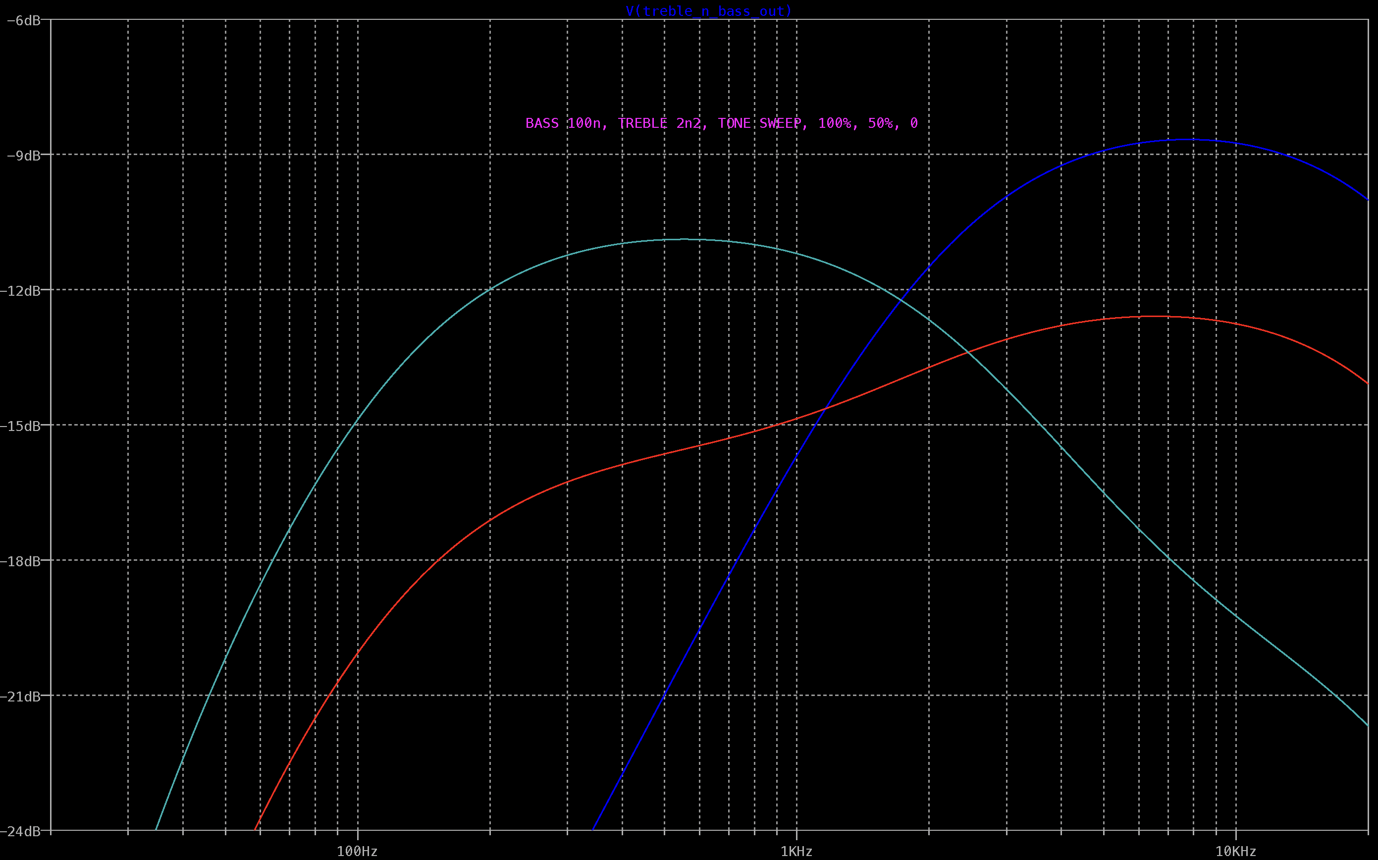
MKIII TREBLE N BASS VALUES
A lot of the character of the pedal comes from the filter section. I think it's fair to say that apart from the fuzz itself, this is the most important tone shaping section of the circuit.
Below are the frequency responses of some of the more common values found, with the tone pot in the centre position and swept to either side. Increasing C5 lowers the high-pass filter / corssover point of the treble and bass, bringing more high-mids into the mix. A side effect of this is that the treble side also gets louder, which can be balanced by the bass side to some degree, but it might also be worth increasing C3 to offset the change.
Like most people, I've never even seen an original MKI in the flesh, so I'm relying on online references for this. The references below all relate to original MKIs - or pedals that are said to be direct replicas of originals built for Sola Sound.
Please feel free to comment and point me in the right direction if you think there's something I should correct or add - ideally with a link to a reference somewhere. Unfortunately, there are only a handful of MKIs left in existence, so new reference material is difficult to come by.
GENERIC MKI TONE BENDER SCHEMATIC
This is the basic schematic for all MKI Tone Benders, with or without R5 & R11and C3 is sometimes electrolytic. Yes, I know the pots were 47k and 470k, but hey...
I'm certain that anyone who has found their way to my blog has seen the Dave Main schematics, the gospel for Tone Benders. As it happens, there seem to be some other values floating around out there from original MKIs that are not well documented - hence this post.
Apart from a number of small variations that are to be found, I believe that there are three basic types of MKI circuits that roughly match different production periods - for want of better names and to match the existing schematics out there, they are the;
Wooden box
Gary Hurst
Sola Sounds
There are variations even across these three - despite the variations, they can still be grouped together largely based on capacitor values and production methods.
The Wooden Box
The wooden box is the earliest of all Tone Benders - and of course very few still exist. This is what I think sets them apart from others;
Constructed on vero board & gooped
3 x OC transistors - exact type unknown, thought to be OC75 or similar
22n input cap, 22n output cap and 2 x 25u coupling caps
33k resistor across Attack pot
The wooden box circuit is the basis for a lot of Stu Castledine's MKIs, as he happens to own one that was rehoused in a metal enclosure at some stage. The information above is based entirely on Stu's MKI builds - there are some minor variations between builds, so take this as general guidance only.
The 22n input cap and the two 25u coupling caps let a lot of additional low-end signal through at the start of the chain, which is then reduced by the smaller output cap.
The last of the line - this is when Sola Sounds appears on the front of the metal enclosure. Very similar to the previous, but with a few changes to biasing and coupling caps.
Point to point on phenolic board
1 x Mullard OC75 & 2 x Texas Instruments 2G381 transistors
All MKI Tone Benders have a 10n input cap right? Apparently not. Stu Castledine's very early version has 22n input and output caps. Dave Main's Phoenix has a 68n input cap and more recently, one has appeared with a 4uf cap - did it leave Macari's like this, who knows? The MKI based Marshall Supafuzz also used a large input cap, so maybe...
These changes both make a significant difference to the sound, as more low-end is making to Q2, which is where a lot of the magic happens.
C3 - COUPLING CAP TO Q3
Values spotted: 50n, 100n, 25u & 40u
HPF
40u 8k2 = 0hz
25u 8k2 = 1hz
100n 8k2 = 194hz
50n 8k2 = 388hz (maybe)
NOTE: This is just the RC filter calculation - when a leaky transistor is added, these values will increase by varying degrees. Check out the detailed calculations here
It's the change from a large electrolytic cap to a 100n cap that really makes a difference. The higher cut-off of the HPF before that last transistor has a noticeable effect on the tone.
C4 / R10 - OUTPUT CAP / HPF
C4 and R10 form yet another HPF - most MKIs have 100n here, with either a 47k or 56k resistor for R10.
HPF
100n 56k = 28hz
100n 47k = 34hz
47n 56k = 60hz
22n 47k = 154hz
22n 33k = 219hz
The 22n output caps are only found on the wooden box version, which is paired with larger input and coupling caps - the HPF is removing some excess bass. It does not sound thinner by any measure.
TUNING NOTES:
These are my notes from breadboarding and spending time testing a lot of transistors + a bit of reading on the internets. Your results may vary. If your MKI is not sounding good, the first place to look is the transistors, and the bias of Q2.
Q1
Just a buffer really - there are minor differences with any transistor that will work in this position. Need some leakage here. OC75s usually leak like sieves.
Q2
Spend time getting Q2 right - it's perhaps the most important transistor in the circuit
Full attack - voltage will drop from close to 9, down to about 5 (in very round figures).
Q3
Affects the general character of the fuzz, including high-frequency content. Lower gain and leakage reduces fizz and scatty note decay (and can act as a noise gate). Despite Q2 doing most of the work, Q3 is still pretty important.
BIAS RESISTOR R3
Anywhere between 180k - 470k have been used. Adjust to taste and your transistor stock.
ATTACK POT
Not unlike the bias resistor - if you have to tune it to taste with R5, there's nothing wrong with that. Smaller bias resistor (R3) can mean smaller pot value. Log pots are recommended by some.
Parallel resistance for the Wooden Box & Gary Hurst versions
50k pot + 33k resistor = approx 20k
The Sola Sounds version does not have the additional resistor across the 50k Attack pot.
Do not expect a nice even sweep of fuzz across the range. It can happen, and it's nice when it does, but sometimes it doesn’t work out like this (log pots often fix this). Note the video below for a demonstration of this, using original Tone Benders.
SYSTEM MKI TUNING TIPS FROM SEEKER ELECTRIC EFFECTS
So nice that this was shared
REFERENCE VIDEO BY GRAHAM GREEN - ORIGINAL TONE BENDERS
ADDITIONAL REFERENCES: RECENT BUILDS FOR MACARI'S (LATE 2022)
Nice bit of MKII history on fuzzboxes.org The MKII might be the most popular of the Tone Benders, although personally I'm split between the MKI & MKIII.
Apparently, this resistor was used to shave a bit of gain off circuits that were prone to making unpleasant noises when Attack was set to full. It's said that this was only on some short board Solas, and some Marshall Suapfuzzes.
C6
My experience with this circuit is that if you don't have a cap on the power, it can oscillate/make terrible noises.
TONE BENDER MKII LEAKAGE & HFE
A lot of talk about this - I'm not going to get into absolutes, but keep in mind that these originally used quite leaky transistors, and there are reports of nice sounding ones with very high hfe.
APPROXIMATE VOLTAGE RANGE
As the heading suggests - these are approximate voltages only. Results will vary from unit to unit, and if it sounds good to you, then don't stress about some numbers.
-4.5 to -5 volts is not what you're after on Q3 collector - that's fuzz face territory.
You can also do it by ear, which is much more fun. Get the MKII running into a clean amp at a reasonable volume. Set the Level full and the Attack totally off. Roll your guitar's volume control back a wee bit, about 7-8 if you have a Strat. The tone here should be pretty clear and clean, if you can hear some fuzzy artefacts then inch the trimmer over to the left until they disperse. If you then crank the Attack and pull up your guitars volume you'll also have maximum sustain from the unit, that too should give a little play on any temperature fluctuations.
FUZZ FACE VARIANT SCHEMATIC, INCLUDING MK1.5 & VOX TONE BENDERS
The schematic includes room for components not present on a standard fuzz face, as some variants have additions.
I thought I'd keep it relatively simple and not venture into circuits with input blends or the various trimmers substituted for resistors (at least for now anyway). R1 & R3 are where trimmers are often placed - usually more frequently as R3, sometimes in combination with a low-value resistor. R4 can also be fun to play with, to help fine-tune the circuit.
No attempt has been made to list every transistor ever used in a fuzz face.
FUZZ FACE VARIANT COMPONENT TABLE
FUZZ FACE TRANSISTORS
Of course, you can't mention fuzz face without talking about transistors. It's definitely a matter of taste - some folks like high-gain silicon, others will settle for nothing but NKT275.
A lot of info out there on forums etc talks about the "best" hfe combination - just ignore that and trust your ears. Lower hFE for Q1 and higher for Q2 is valid advice. Some say keep the hFE about 20 to 40 apart
Very low leakage germanium transistors have given me good results, especially for Q1. In my experience, very low leakage on Q1 gives the best clean tones.
The Mythical NKT275
Good luck finding real ones. Interesting quote from Analog Man here re the NKTs. The man knows his transistors and fuzz faces.
"The sound of these original NKT275 transistors was quite similar to the other types of germanium transistors that we use. But the NKT275s have less fuzz, and less high end fizziness. They have a deeper tone and clean up better than most transistors. If you turn down the volume on your guitar, the NKT275 sound will be totally, sparkly clean without any fuzz remnants. Normally, NKT275 transistors are not high gain, that is why they clean up so well and are so smooth sounding."
AC128
They did appear in some reissued fuzz faces at one stage, but most experts out there are yet to see one in a proper vintage fuzz face. The general advice is to avoid the AC128.
VOLATGE
As for the magic Fuzz Face number of -4.5v on the collector of Q2 - it's a good start, but don't stress about it. I tested a really nice Fuzz Face from the first year of production measuring -5v (NKT275 transistors). It sounded great.
If you're making a MK1.5 using OC75s - it's going to be a much higher voltage, due to leakage. Don't bother trying to get it to -4.5v. It's not going to happen.
VOLUME MOD
A common complaint is that the volume too low.
R2 & R3, usually 470 and 8k2, form a voltage divider from the collector of Q2 to DC supply. AC isn't fussy about where ground is - this means that you have a hardwired volume control before the actual volume pot, which is reducing the output level by a massive amount.
8,200 + 470 = 8,670. So just adjust the resistor values to add up to around the same amount. The most common thing to do is change the 470 to a 1k resistor.
Replacing the 8k2 with a trimmer is also another solution - this often changes the bias. You might like the output level, but then find you prefer the fuzz sound when the level is lower. Anyways, whatever works right...
THE ANALYSIS OF, AND THE DARK ARTS OF THE FUZZ FACE
I used Kit Rae schematics, but I did not follow the same component numbering, as I don’t find it all that intuitive. Kit did it that way for a good reason, this way works better for my brain. There's also this excellent post by Kit Rae on the EHX forum, broadly describing differences between versions.
GENERIC BIG MUFF SCHEMATIC
ELECTRO-HARMONIX BIG MUF PI COMPONENT VALUES TABLE
If you want to add power filtering, just add an extra row at the top - if you're read this far, I'm sure you can work it out.
GENERIC BIG MUFF LAYOUT
There's room for the tone pot to be wired on the sides of the vero board, I prefer them to be together, which is why they're popping up out of the middle of the board at the top.
There's enough room on this to add power filtering and polarity protection down the centre two rows (where V+ and ground is).
GENERIC BIG MUFF SCHEMATIC WITH CAPACITOR POLARITY MARKED
BUILD TIPS
There are no magic parts in a Big Muff. It's a well designed circuit and the fact that so many value changes occurred over time and it still sounds like a Big Muff is testament to that.
Transistors
Don't stress about getting the "right" transistors. There's really quite minimal differences between most transistors - certainly don't spend a lot of money on rare / vintage for a Big Muff. I know there are lengthy online discussions around what the right hfe is, after spending a lot of time testing on a breadboard with guitar in hand, I decided that it doesn't really matter that much.
Diodes
Again, subtle differences for the most part. Practically any small signal silicon diode does the job.
Resistors & Capacitors
Values are important, the type is not.
I will say that some of the odd values seen on the filter section are worth trying to attain. example 4n and 12n. If you substitute different values, it will obviously still work, but it doesn't sound the same - the filter section is such a big part of the Big Muff sound.