I’m surprised I had not covered this one before, but I suppose it is a MKI, so it should feel fairly familiar.
There seem to have been a few different iterations — essentially just different flavours of the MKI, so keep that in mind when choosing transistors and biasing the circuit. Some versions also used the more familiar point-to-point MKI style board.
Basically it cuts the output limiting resistor in half, from the stock 2.2 Meg down to 1 Meg. The first batch of the new 2015 1965's that went to Joe all had approx 1.5 Meg limiting as stock and the Super Zee bypassed it entirely.
Also worth noting from another post: What no side switch? This is correct. It was making my tuning of the pedal a little erratic at times.
I have not listed transistor types, because they varied, and the chances of you having the exact same transistors D*A*M used — and for them to sound great in a MKI anyway are fairly small. Even from reading posts on the D*A*M forum, Dave appears to have moved away from using 2 x OC75s in this circuit because they were less stable than other options - and you can be pretty sure that D*A*M has a larger selection of transistors to choose from than you or I.
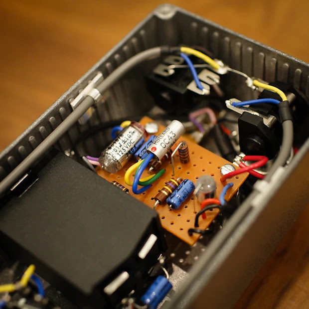
So this looks like one of the D*A*M one-offs from back in the day - a MKI style fuzz, using a variation on a Zonk layout. There are some departures from stock values, some of which are not entirely clear.
There are a few components that are not visible, but if you have any build experience, you can make some reasonable assumptions. Pop it on a breadboard... I know that's what I'm about to do.
One thing that throws me is this - the resistor next to the OC45 (the Q2 collector), is it brown green red gold, (1k5) or purple green red gold (7k5)? I think 7k5, the schematic on FSB says 1k5.
On the breadboard, 7k5 works just fine, so I'll stick with what I see and hear. Can't always trust what you find online, including here ;-)
Quick Zonk Machine layout to suit an enclosure that I just picked up from MW Pedal Parts - pretty much one row difference in terms of where the mounting holes are drilled compared to old layout that I have been using, and I decided to move a couple of components around while I was at it.
MW are great by the way - no hesitation in recommending them based on my experience. The ordering process is a little unusual, but they deliver on the goods.
I'm jotting down some notes for myself, because I don't expect anyone else to use this layout. It's a little impractical in parts, but I had some spare board this size, and a pair of transistors that I liked on the breadboard that needed a home. It's a progression on this somewhat more practical layout.
Notes: all links under the board. Maybe reduce the 10k bias pot a little with a parallel resistor. Cleans up well, solid fuzz. Breadboard values: 1k / 6k8, maybe 5k6 at around 30 degrees. 10uf bypass cap, battery 8.5v
Just a Fuzz Face layout that I used recently and want to make note of - it's based on the one knob fuzz line, which is a handy little layout, but didn't quite suit my needs. With some minor adjustments, it can be used for most fuzz face variants - component table here.
FUZZ FACE - 0.15" VERO LAYOUT - BE V1
The photo doesn't exactly match the layout above, as I routed some wires through the holes and under the board to make things a little neater, and I updated the layout after making the first one. There were also some component value tweaks.
Since I'm doing boosters at the moment - the D*A*M Supa Rooster.
I'd suggest placing a 1m resistor on the input and output if you get switch pop - a lot of people do this all the time for their rangemaster type circuits. If you want it to look true to the original, use 1/4w metal film resistors and sneak them under the board.
Pretty much the same layout as the D*A*M pedal, can't see the value on a few components, but safe to say, that anything in the normal area of a rangemaster will be just fine. I'm talking pot values and the smaller input capacitor in particular.
Nothing groundbreaking today—just a variable-gain germanium booster I through together this afternoon, heavily inspired by the D*A*M Red Rooster.
I built mine on a slightly different layout, but if I do another one I’ll use this version; it’s cleaner and a bit easier to wire. And if you like the idea of incorporating a trim pot instead of the 3k9 resistor, I'm sure you can work it out.
Thanks to the “range” pot, the top-end never gets as thin as a typical treble booster: a little signal always sneaks across the pot into the 1µF cap. That gives you a smooth sweep from bass-trimmed sparkle to a rich, full-bodied soft fuzz—and it sounds sweet at every stop along the way.
The enclosure was a gift and came pre-drilled, which is why the jack holes sit so high up the side—strange and somewhat inconvenient placement, but it does the job.
I hid the 1m resistors under the board to save a bit of space, and I didn't have the same type as the 470k and 68k. The 1m on the input and output almost eliminate switch pop, which tends to happen on rangemaster style circuits.
It's no secret as to what the R2R Electric germanium preamp is based upon, which is an old and very rare Hofner preamp. The Hofner is a full-range germanium booster, which was once used as a way to plug guitars into old console radios way back in the day.
As this is a simple Rangemaster style circuit, any layout used for a Rangemaster could be used instead of the one below.
R2R ELECTRIC GERMANIUM PREAMP LAYOUT
R2R spends a bit of time testing every component used, to get the sound that they're chasing. Since not all components are created equal, it’s worth dedicating time to testing and selecting components to ensure you get the most out of this simple circuit.
One notable choice is the AC107, which R2R recommends as a low-noise, higher-quality alternative to the OC44 or OC71 commonly used in Rangemasters. This decision is practical: while OC44s are highly sought after due to their use in Rangemasters, they’ve become increasingly expensive and are often prone to noise issues.
Side note: An excellent podcast featuring Chris from R2R can be found here on the Fretboard Journal. Chris talks about his journey and process.
And thanks to the person who very kindly helped out by sharing some photos of their pedal, confirming that the boost pot is wired the same way as a Rangemaster.
I built it on tag strip, using the same layout - works just fine. If you do the same, careful with the size of the caps either end as it’s a very snug fit in a 1590B
Boost / Volume pot: R2R implemented the volume/boost control in the same way as the Rangemaster. The stock Hofner circuit uses a 10k resistor to the collector and has no volume control - R2R replaced the 10k resistor with a 15k pot. If a 15k pot is hard to source (as it's an uncommon value), try a 25k pot with a 39k resistor across pin 1 & 3 - this will drop it down to 15k. Any resistor between 33k - 50k will get you close enough to 15k. Pots are rarely bang on spec, so not something to stress about. You could also experiment with a 10k pot to see how it goes.
Input resistor: There's no need to worry about using the exact value for the input resistor. The stock Höfner schematic specifies 37k, which is an unusual value. R2R opted for 36k. As long as your choice is close, it should work fine.
It’s worth noting that the input resistor forms a voltage divider with the 10k resistor connected from the transistor base to ground. Together, these resistors reduce the input signal by about 80% before it’s amplified by the transistor.
Emitter resistor: The stock Hofner circuit uses a 1k5 emitter resistor, but there's room for variation, which can be tuned to match your chosen transistor. The R2R layout uses a 3k9 resistor, like the Rangemaster. Smaller values are more likely to produce some dirt, while larger values will result in a cleaner sound. This is a great spot to use a trimmer pot if you want adjustable control.
Capacitors and Bias Resistors: The capacitor values and the 100k/10k bias resistors remain consistent across designs. However, there's flexibility with the capacitor values:
The input capacitor can be reduced significantly without noticeable changes in response. For instance, 1u is nearly indistinguishable from 4u7.
The 100u emitter bypass capacitor can be reduced to 47u with minimal impact.
Similarly, reducing the output capacitor slightly will have negligible effects on the sound.
Of course, collectively changing a lot of component values at once will increase differences, but ultimately, it is just a fairly generic single transistor booster in therms of the circuit.
Drop down resistors: R2R included 1M input and output drop-down resistors wired to the stomp switch, which you can see in the photos below. These are not present in the Höfner circuit but are a common addition to prevent switch pops. Including them is recommended.
Board: I’ve not listed the size of the board or any other info on the point-to-point layout - I’m sure you can work that out yourself.
Images below from a prototype - the 1k5 resistor may not have made it into production models.
Here’s a simple Rangemaster treble booster. I’m jotting down some notes from my recent builds because I really dig this layout. I used a 1590BBS enclosure and an 8-way tag strip. It’s pretty similar to the Pigdog Eel Pie layout, which inspired my design.
Inside, you’ll find a Mullard OC71 transistor. But honestly, the specific transistor isn’t a huge deal—pretty much any PNP germanium transistor will sound great in a Rangemaster. You definitely don’t need an OC44 to get that sweet sound.
What really makes this pedal shine is a couple of key factors:
Hitting Your Valve Amp Hard: The Rangemaster works best when you crank it into the front of a valve amp.
Adding Harmonic Distortion: That germanium transistor adds some nice harmonic distortion, which enriches the overall tone.
For the best results, pair it with a valve amp that’s just on the edge of breakup or slightly dirty - there's always a bit of a balancing act between the amp and the boost level. Once you find your happy place, set and forget. Keep in mind that once the amp is clipping, it doesn't really get louder, it gets more saturated, and some bass is trimmed off the signal - for many people, this is the sound that they're looking for.
If you run it into a super clean amp—especially a solid-state one with lots of headroom—you won’t get great results, as it just sounds thin.
Which looks like this in practice.
There's just enough room in there for a battery, but I decided to skip it for this one.
I saw a post today about leakage and temperature, so I thought I'd do a quick test myself to see how close it came. The test distinctly lacked scientific conditions - for starters I wasn't even wearing a white coat at the time, but the results seem to match the theory.
For germanium transistors, leakage current mainly depends on temperature and doubles for every 10°C rise in temperature.
Measurement #1: taken in my garage / workshop after it had been closed up all day - it's not very well insulated, so it gets really hot. The temperature was probably about 40 degrees (ambient temperature outside was high thirties).
79hfe, 0.32mA leakage
Measurement #2: Same transistor about an hour later after sitting in very cool air conditioning, I'm guessing, but it's probably about 20 degrees in the house, so I'd say close to a 20 degree difference to the first reading.
hfe 69, leakage 75ua (or 0.075mA).
Given the first reading was 320mA and the second was 0.075mA, doubling every 10 degrees seems to hold true.
WHAT'S THE POINT?
If you're working with germanium transistors, try and work in normal conditions (a reasonable room temperature). If you have a circuit sitting just on the edge of gating at 35 degrees, it may not work at 15 degrees. Likewise if noise is a concern at a low temperature due to leakage, it's going to get way worse when it heats up.
Valvo transistors were produced in Germany, as a subsidiary of Philips (not unlike Mullard in England). More information on Valvo can be found here. My experience with Valvo, is that they are pretty much identical to their English counterparts.
The OC45 is a PNP germanium alloy transistor intended as IF amplifier in AM broadcast receivers.
Just a Rangemaster with a rotary switch for selecting input capacitors - it uses some odd parts, as this is what was available in my local electronics store - the 5 lug tag strip in particular, a regular Rangemaster is on 6. It's also a slightly odd rotary, but it was all that was left in the draw.
RANGEMASTER BASED GERMANIUM BOOSTER - VARIABLE FREQUENCY
You may also want to add a small cap ( 470p / 1n) across the input to the base of the transistor, so there’s always a capacitor in the circuit - this reduces switch noise on the rotary. I don’t think it’s massively important, as I’m a set and forget kind of guy.
Do check the numbering on the rotary, as the ones that Ive been using are in reverse, compared to the layout. i.e. start with small cap values on the left.
Expect some hiss - this circuit is infamous for it, but it does sound good so most people overlook this. Having a rotary with a few capacitor options is so much better than the stock Rangemaster treble booster - the additional range of sounds is well worth it. The full range boost can get a little fuzzy, which is something that I was not expecting.
While it was pretty quick to put the Rangemaster board together, it wasn't fast to wire up the rest. There was a bit of fiddling with lining up the capacitors on the rotary, and the general position of the tag strip didn't help matters.
Same again, but this time with a pot to help set the gain, instead of a 3.9k resistor. This is hand to dial in (or out) the grit that can really make treble boosters shine.
GEC is the General Electric Company of England, not the one from the U.S.A. These are occasionally branded as Mullard. Full write-up on GEC / GET transistors can be found here
GEC GET 102 - 114 GERMANIUM TRANSISTOR DATA
TypeV MaxHfeP Max (mW)I Maxf (Mhz)
GET1023010020010001.5
GET103305520010001
GET104305520010001
GET105403080010000.9
GET106155520010001
GET110402080010001
GET111605520010001
GET1131510020010001.5
GET114155520010001
TRANSISTOR EQUIVALENTS
Anything from the red colour range from GEC is an audio amplifier; they're listed as being similar to a number of common transistors, such as the AC128.
Brimar transistors were made by Thorn and were also commonly branded as Mazda. A full write-up can be found here
The AC113 is an audio frequency amplifier or driver type germanium transistor.
AC113 GERMANIUM TRANSISTOR DATASHEET
TRANSISTOR EQUIVALENTS
Being a fairly generic audio amplifier, they're listed as being similar to a number of common amplifier transistors, such as the AC125.
WHAT ARE THEY REALLY LIKE?
Testing results from a lot of 10: The range of gain and leakage is huge - from 45hfe with very little leakage, right up to 330hfe with a lot of leakage. Several were a bit over a 100hfe with moderate leakage. One was dead, only useful as a diode.
So if you see some going cheap and are tempted to grab a few, buy more than you think you will need, as there will most likely be wastage.
Following on from the previous post, this is the D*A*M version of the Colorsound Fuzz Sound. Thread on the D*A*M forum can be found here. Basically take a D*A*M Fuzz Sound, and change the Fuzz pot to an internal trimmer.
Unlike the regular Park 2 knob with a large 25u coupling cap between the darlington pair and Q3, D*A*M has stuck with the stock 220n cap. However, the cap from the emitter of the darlington pair to ground has been increased, which provides a bit of a bass boost. There's also the bigger caps in the filter section, often used by Dave Main, which is also my favourite set-up. It just drops the cut-off of the high pass filter on the treble side down and helps with the bass response. It also has a smaller resistor between the tone and volume pot.
So despite the smaller coupling cap, this has been accounted for elsewhere.
Request for Phil - one tag board layout for the Park 2 knob fuzz sound. I generally prefer to keep the links below the board, as it looks neater. I don't mind linking two adjacent lugs on top, as you hardly notice it.
One suggestion for this. The D*A*M Colosround Fuzz Sound has a few different values and an internal trimmer to fine-tune the fuzz. They say that it's set at about 90% - so given that the pot is normally 100k, you could use a 10k resistor instead of a link under the board, or any value resistor of your choice.
I only came across the Hofner Preamp quite recently, despite seeing some other builders making point-to-point style germanium preamps based on this circuit - the prime example being the R2R Electric preamp.
There's a good write up here, but in summary: Back in the day before guitar amps were affordable, and TV was a thing, pretty much everyone had a big valve radio in the house. Many had an input for turntables, but most people didn't have a turntable as they were expensive. So Hofner made a preamp to allow early electric guitars to be plugged into a valve radio, via this additional and often unused input.
The preamp boosts signal and helped fix the massive impedance difference, turning the family radio into a primitive guitar amp.
Worth noting that old record players had a much higher output than the current ones, hence the need for a boost. The output was so high, that when you look at old schematics for valve PA systems, the P.U. input skips the first 12AX7 gain stage, and goes straight to a mixer, so guitars really needed an extra boost to make it work.
HOFNER PREAMP SCHEMATIC
It kicks out a good 20dB of boost and has a relatively flat response
I'd be very surprised if the boost is as clean as it looks on LTspice - I'll have to breadboard this and check it out on the scope. I'm sure there would be some dirt.
MODS
I guess the first and most obvious is adding a volume pot. A 220n output cap is pretty healthy, so a standard A100K volume pot will work just fine. Note the R2R electric method, which is similar to a rangemaster. This is probably a better way to do it.
Reducing R1 increases the input level, as it normally forms a voltage divider with R2. Things will get a little fuzzy and overdriven.
C1 can be reduced to treble booster territory.
C4 can be reduced for a bit of low-end roll-off.
TAGBOARD & VERO LAYOUTS
The original was constructed in a very similar fashion to the Rangemaster - a simple point-to-point circuit in a box.