Showing posts with label TREBLE BOOST. Show all posts

Thursday, December 25, 2025

GUILD / CORNISH: Silicon treble booster

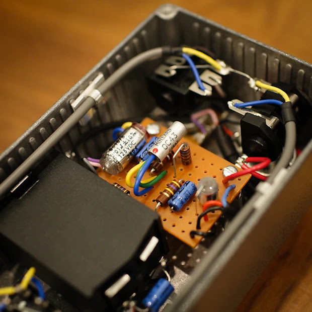
As I was recently playing around with the Colorsound booster made by Steve Williams of Pig Dog fame, I noticed some similarity to the Guild Treble Booster, AKA the Brian May Box.

I made a slightly simplified version of the Guild, without the buffer based on one of the Fryer Boosters.  I kind of free-styled the build, working without a layout using a spare piece of vero. 

This is going into a Hammond 1590B enclosure, which is normally too small for anything that I make.  This will just have an on/off switch and no knobs.

I used a vintage glob top NPN silicon transistor pulled from an old PA head preamp.  While I listed a BC107 on the vero layout, almost any silicon NPN transistor will work - all the common ones certainly do.  


SILICON TREBLE BOOSTER - VERO LAYOUT

I tweaked a few values and moved some parts around on the board after the photo was taken - will update with some new photos while boxing this up.

The links are placed under the board, primarily for looks - and same for the standing resistors. 

SILICON TREBLE BOOSTER - VERO LAYOUT


C1.  This controls the bass cut on the input.  i.e. it shapes the treble boost.   

C5 rolls off high frequencies at the output, which may seem a little counterintuitive for a treble booster, but I quite like it.   

C2:  A smaller cap can be used for C2, with no real change - 100pf would be fine as an example.  

C3 - 22uf will also do the job.  


And just to confirm that it's a booster...  440hz sine wave used with a 6n8 input cap, 3n3 output cap

R5 and R6 control gain - the circuit started with 6k8 and 2k4 in these positions.  I moved to 10k and 2k2 as they're more common values, and it gave a bit more output.


Just as a side note:  the Guild treble booster also appears as the boost in the Vox Brian May AC30.  Albeit with a high/low boost switch, which just adds 10k series resistance to ground on the 47u bypass cap.  


Monday, September 29, 2025

COLORSOUND: Treble Booster, Steve Williams (partial trace)

So there are a few bits missing, but if you are familiar with treble boosters, I'm sure you'll work it out.  Being a small and simple circuit, it's a good candidate for breadboarding.

The filter pot is your standard input blend, probably similar to the values that Steve Williams uses in his Pigdog Competition Special boosters, which is followed by a silicon treble booster with a coupling cap and volume pot attached to the end.  So a little different to a Range Master in that sense.  It's more akin to the Guild Treble boosters

Updated layout:  Thanks Zollinger Analog for pointing out that there is actually a link between pins 1 & 2.   I couldn't see what was right in front of me...  the link is sitting on the other side of the pot.

COLORSOUND TREBLE BOOSTER - STEVE WILLIAMS

COLORSOUND TREBLE BOOSTER - STEVE WILLIAMS

Important to note that this is a partial trace - you may have to test this and work a few things out yourself.

COLORSOUND TREBLE BOOSTER - STEVE WILLIAMS


With a 5n / 100n cap and a 100k filter pot, the response on the base of the transistor looks like this.  The output looks about the same with the 100n and 100k pot.  A 47n cap looks pretty similar as well.

COLORSOUND TREBLE BOOSTER - STEVE WILLIAMS - FREQ RESPONSE

Being a silicon boost, they tend to be a cleaner wave than a germanium boost, although this does look to get some dirt as more bass is introduced.  It is just a simulation, so real-life results may differ - and honestly, you never want to hear a silicon treble boost that is not overdriving an amp - horrid...  

COLORSOUND TREBLE BOOSTER - STEVE WILLIAMS - WAVE


Friday, August 8, 2025

COLORSOUND: 1971 Overdriver

The Colorsound Overdriver / Power Boost family went through a few different versions over the years. This layout is for the classic 1971 9V Overdriver version – essentially the 9V successor to the earlier 18V Power Boost, with the same basic three–transistor topology but set up for a standard single-supply pedalboard. It makes a huge, dynamic boost that can run from almost clean to a thick, fuzzy overdrive, with a very effective bass and treble control.

I went with the 1971 9V spec simply because 9V is more convenient, and I had one of the larger Gapco enclosures that suited the longer 0.15" vero format.  This layout also includes a post-gain volume control (master volume).  Original units did not have this, but given how loud the circuit is, most people prefer to keep the master.  If you really want to be vintage-correct you can omit it and wire the output straight from the gain pot.

There is a lot of excellent historical information on the Power Boost / Overdriver on Kit Rae’s site, including a clear explanation of the differences between the 18V Power Boost and the 9V Overdriver, and notes on various reissues.


COLORSOUND 1971 OVERDRIVER – 0.15" VERO LAYOUT


Layout notes: this is a 0.15" stripboard layout sized for a larger vintage-style enclosure. Check transistor pinouts before soldering – the original BC109 devices can be swapped for common modern NPN types if you re-orient the legs correctly. The added volume control is a true output master; if you omit it, take the output directly from the gain pot lug as marked.


COLORSOUND 1971 OVERDRIVER SCHEMATIC


COLORSOUND 1971 OVERDRIVER VIDEO DEMO

Here’s a short demo of this layout in use, showing the range from clean boost through to full overdrive.

Friday, July 11, 2025

D*A*M: Supa Rooster

Since I'm doing boosters at the moment - the D*A*M Supa Rooster.   

I'd suggest placing a 1m resistor on the input and output if you get switch pop - a lot of people do this all the time for their rangemaster type circuits.  If you want it to look true to the original, use 1/4w metal film resistors and sneak them under the board.

D*A*M Supa Rooster vero layout
Pretty much the same layout as the D*A*M pedal, can't see the value on a few components, but safe to say, that anything in the normal area of a rangemaster will be just fine.  I'm talking pot values and the smaller input capacitor in particular.  


Sunday, July 6, 2025

Germanium Variable Booster

Nothing groundbreaking today—just a variable-gain germanium booster I through together this afternoon, heavily inspired by the D*A*M Red Rooster.

I built mine on a slightly different layout, but if I do another one I’ll use this version; it’s cleaner and a bit easier to wire.  And if you like the idea of incorporating a trim pot instead of the 3k9 resistor, I'm sure you can work it out.

Thanks to the “range” pot, the top-end never gets as thin as a typical treble booster: a little signal always sneaks across the pot into the 1µF cap.  That gives you a smooth sweep from bass-trimmed sparkle to a rich, full-bodied soft fuzz—and it sounds sweet at every stop along the way.


Gernamium Variable Booster

The enclosure was a gift and came pre-drilled, which is why the jack holes sit so high up the side—strange and somewhat inconvenient placement, but it does the job.


I hid the 1m resistors under the board to save a bit of space, and I didn't have the same type as the 470k and 68k.  The 1m on the input and output almost eliminate switch pop, which tends to happen on rangemaster style circuits.


Monday, October 7, 2024

DALLAS: Rangemaster, 8 lug tag strip version

Here’s a simple Rangemaster treble booster.  I’m jotting down some notes from my recent builds because I really dig this layout.  I used a 1590BBS enclosure and an 8-way tag strip. It’s pretty similar to the Pigdog Eel Pie layout, which inspired my design.

Inside, you’ll find a Mullard OC71 transistor. But honestly, the specific transistor isn’t a huge deal—pretty much any PNP germanium transistor will sound great in a Rangemaster. You definitely don’t need an OC44 to get that sweet sound.

What really makes this pedal shine is a couple of key factors:

  1. Hitting Your Valve Amp Hard: The Rangemaster works best when you crank it into the front of a valve amp.
  2. Adding Harmonic Distortion: That germanium transistor adds some nice harmonic distortion, which enriches the overall tone.

For the best results, pair it with a valve amp that’s just on the edge of breakup or slightly dirty - there's always a bit of a balancing act between the amp and the boost level.  Once you find your happy place, set and forget.  Keep in mind that once the amp is clipping, it doesn't really get louder, it gets more saturated, and some bass is trimmed off the signal - for many people, this is the sound that they're looking for.

If you run it into a super clean amp—especially a solid-state one with lots of headroom—you won’t get great results, as it just sounds thin.


Rangemaster tag strip 8 lug layout


Which looks like this in practice.

Rangemaster gut shot

There's just enough room in there for a battery, but I decided to skip it for this one.


Monday, October 2, 2023

RANGEMASTER BOOSTER

Just a Rangemaster with a rotary switch for selecting input capacitors - it uses some odd parts, as this is what was available in my local electronics store - the 5 lug tag strip in particular, a regular Rangemaster is on 6.  It's also a slightly odd rotary, but it was all that was left in the draw.

RANGEMASTER BASED GERMANIUM BOOSTER - VARIABLE FREQUENCY

RANGEMASTER BASED GERMANIUM BOOSTER - VARIABLE FREQUENCY

You may also want to add a small cap ( 470p / 1n) across the input to the base of the transistor, so there’s always a capacitor in the circuit - this reduces switch noise on the rotary.  I don’t think it’s massively important,  as I’m a set and forget kind of guy.  

Do check the numbering on the rotary, as the ones that Ive been using are in reverse, compared to the layout.  i.e.  start with small cap values on the left.


RANGEMASTER BASED GERMANIUM BOOSTER - VARIABLE FREQUENCY - BUILD PHOTO


Expect some hiss - this circuit is infamous for it, but it does sound good so most people overlook this.  Having a rotary with a few capacitor options is so much better than the stock Rangemaster treble booster - the additional range of sounds is well worth it.  The full range boost can get a little fuzzy, which is something that I was not expecting. 


While it was pretty quick to put the Rangemaster board together, it wasn't fast to wire up the rest.  There was a bit of fiddling with lining up the capacitors on the rotary, and the general position of the tag strip didn't help matters.   

Same again, but this time with a pot to help set the gain, instead of a 3.9k resistor.  This is hand to dial in (or out) the grit that can really make treble boosters shine. 


Saturday, February 4, 2023

PETER SINGFIELD: Treble Booster (a quieter one)

I came across this while browsing one of the usual forums recently and thought it looked like an interesting Rangemaster variant.   Silicon or germanium transistor, variable boost, quiet, standard power supply...  seems to have a lot going for it as far as treble boosters go.   

Here's the thread on DIY Stompboxes (Peter is FSFX) and there's this documentation detailing the noise reduction.

Naturally the input caps can be tuned to taste, and the range pot can be completely removed or replaced by a switch if that's your preference.


PETER SINGFIELD - A QUIETER TREBLE BOOSTER - VERO LAYOUT

PETER SINGFIELD - A QUIETER TREBLE BOOSTER - GUITAR EFFECT VERO LAYOUT RANGEMASTER


Thursday, May 12, 2022

JOHN HORNBY SKEWES: Shatterbox, 0.15" Vero Layout

Continuing with the Hornby Skewes theme, time for the Shatterbox - original layout below using the old school large format 0.15" stripboard.  Although I'm not sure if I actually want to build one this way...  apart from all the off-board components, it's PNP silicon, which is annoying having a positive earth circuit with none of the benefits of germanium transistors.

HORNBY SKEWES SHATTERBOX - ORIGINAL 0.15" VERO LAYOUT

HORNBY SKEWES SHATTERBOX - ORIGINAL 0.15" VERO LAYOUT


Photo from freestompboxes for comparative purposes below - a thread can be found here.  Scroll down for the rest of the photos and the schematic on the FSB thread, as it actually starts with someone building one (pinkjimiphoton), not liking it and coming up with an improved design.

The original design has a 100k resistor to ground across the output jack, subsequently affecting all signal through the pedal - so this is not in the true bypass camp as it stands.  It will affect your signal, whether it's on or off.   

I suggest you modernise the switching if you choose to build it, and while you're doing that, you may as well make it NPN and add some LEDs.  Just remember to flip the polarity of the electrolytic caps if you do.


HORNBY SKEWES SHATTERBOX - ORIGINAL 0.15" VERO LAYOUT


SHATTERBOX VIDEO DEMO


JOHN HORNBY SKEWES: Selectatone TB2 Treble and Bass Booster, Tag Board Layout

While on the JHS thing, I noticed this booster and thought it looked interesting.  The output switches between filters to allow for treble and bass boost, unlike most other boosters where it all happens at the input.

Very few seem to be around, as I could only find one photo of the internals and one video demo.  The schematic still has a couple of assumed (but working) values, which are explained below and marked on the layout.

There's a bit of off-board wiring, which is how the original was built - and no volume control.  

JOHN HORNBY SKEWES SELECTATONE TB2 - TAG BOARD LAYOUT

JOHN HORNBY SKEWES SELECTATONE TB2 - TAG BAORD LAYOUT


Image credit: Effects Database https://www.effectsdatabase.com/model/jhs/selectatone#


LTSPICE RESULTS

Both with 100n for the input cap (C1), and the cap linking the treble bass switch (C2).


Changes to the 100n caps (C1, C2) mentioned above have almost no impact on the frequency response of the treble boost (right down to 22n), so tweaking these caps is more around tweaking the bass boost to your liking, and there will be some changes to how it distorts as well.


I split the circuit into two for bass and treble boost, as switches are painful in LTspice - simple SPDT / DPDT switches don't exist.  

For nerdy folks familiar with spice, here's what I was doing (schematic below).   

Short story for lesser nerds, a smaller C5 cap in the bass boost section raises the boost level and shifts it towards the mid-range.  C2 tunes how much low-end roll-off there is.  i.e. you might want a low-mid boost without the flabbiness of too much low-frequency content.

C1 impacts the response, affecting how the transistor distorts, so it's worth trying a 47n in there and a 100n.

Basically, breadboard it and play with C1, C2, and C5. 


Treble boost vs Bass Boost


Input cap variations effect on the Treble Boost output


VIDEO DEMO


OC71 vs 1T308 TRANSISTORS

Spot the difference?  Someone had a question in the comments, so I thought I'd quickly breadboard it for a look - note that this is from the 100n cap on the output, not after the high pass filter.

So turns out they look almost identical, and voltages also measured about the same.   


Wednesday, May 4, 2022

ANALOG MAN: Beano Boost

The Analog Man Beano Boost takes the classic Rangemaster treble booster and adds a very useful function — a switched input capacitor that widens the tonal range beyond the original’s treble boost.

Because it’s a single-transistor germanium circuit, the choice of transistor does shape the tone and clipping character, especially at higher gain settings.  That said, you don’t need to hunt down an expensive vintage OC44 to get great results.  Many germanium transistors will work really well in this circuit — just be mindful of noise, as a bit of hiss is common with older germanium devices.

Quite a bit of info here on Analog Man's website 


ANALOG MAN BEANO BOOST - TAG BOARD LAYOUTS

ANALOG MAN BEANO BOOST - TAG BOARD LAYOUTS


Same again, but with a pot to control the gain - with the 5k pot at around 50% the series resistance is about 3.5k depending on component tolerances.  I think this is close enough to the stock 3.9k - you could use something a bit larger than 1k to get it closer, but it really doesn't make a massive difference.

This is handy for finding the sweet spot for just the right amount of grit in the boost.  Another useful option is to replace the 68k resistor with a pot (100k as an example).  One of the Steve Williams boosters has this addition - minor downside, the pot has DC on it, so it will sound scratchy / crackly.


ORIGINAL BEANO BOOST LAYOUT

This is the layout used by Analog Man, which is the same as a vintage Rangemaster (excluding power filtering & 1m resistors). 

Note that I've done it in two layers, as it's hard to show parts directly underneath each other in this format.  


VIDEO DEMO


Saturday, January 1, 2022

EARTHQUAKER DEVICES: Bows

The Earthquaker Devices Bows is a straight-up germanium Rangemaster with some modern tweaks.  It uses an NPN transistor and has a switch to swap to a larger input capacitor for a full-range boost.

The space above the transistor on this layout allows it to be mounted on its side (bent over 90 degrees), as OC transistors are pretty tall, and if you use the mounting points, you will need to reduce the height of the transistor in the enclosure.  It's generally a good idea to place insulation on the legs of the transistor so they don't short when you bend them.  If not all the legs, at least the base leg in the centre of the three.


EARTHQUAKER DEVICES BOWS - VERO LAYOUT

EARTHQUAKER DEVICES BOWS - STOMPBOX VERO LAYOUT


Wednesday, November 17, 2021

PETE CORNISH: TB-83 Treble Booster, Point to Point Layout

I followed a vaguely similar layout to the one pictured at the bottom of the post for the Pete Cornish TB-83 Treble Booster.   

This is a straight treble boost using a silicon transistor - it's going to sound horrible into anything apart from a cranked valve amp, or maybe a valve based pedal.  Given this was in Brian May's rig, think normal channel of a cranked AC30, with this hitting it.  Well maybe you aren't running nine AC30s at once, all running so hard the border on catching fire, but you get the idea.


PETE CORNISH TB-83   POINT TO POINT LAYOUT

PETE CORNISH TB-83 - POINT TO POINT LAYOUT


PETE CORNISH TB-83 - LTSPICE

I used the schematic from Fryer Guitars - link here.  

PETE CORNISH TB-83 - LTSPICE


Tuesday, November 16, 2021

GUILD: Brian May Box

The layout is for the Guild Brian May Box, which on the Guild schematic is marked as designed by Pete Cornish, but he has disputed this.

There's a massive write-up here on Fryer Guitars, including photos of inside Brian May's Pete Cornish built pedal board, and inside a pretty vintage looking Pete Cornish treble boost, which also happens to contain a buffer.  Given that Fryer rebuilt AC30's for Brian May and has a few of his own treble boosters, I think the man knows a thing or two.

Either way it's a buffered treble boost.  You can either wire this up as buffered or true bypass, whatever you prefer. 

GUILD BRIAN MAY TREBLE BOOSTER - VERO LAYOUT

GUILD BRIAN MAY TREBLE BOOSTER VERO LAYOUT


GUILD BRIAN MAY TREBLE BOOSTER - ORIGINAL SCHEMATIC

GUILD BRIAN MAY TREBLE BOOSTER - SCHEMATIC


GUILD BRIAN MAY TREBLE BOOSTER - LTSPICE

Not much to see here.


And one difference to other treble boosters from the Rangemaster family is the 10n input cap vs the standard 4.7n.