Showing posts with label MODULATION. Show all posts

Friday, September 30, 2022

EARTHQUAKER DEVICES: The Depths

I think it's fair to say that you should not attempt this unless you are pretty confident with your builds.   The Earthquaker Devices The Depths, is their take on the Uni-Vibe.   


The schematic can be found here, on PedalPCB in the build doc.


EARTHQUAKER DEVICES THE DEPTHS - VERO LAYOUT

EARTHQUAKER DEVICES THE DEPTHS - VERO LAYOUT


THE DEPTHS VIDEO DEMO


Saturday, September 24, 2022

EARTHQUAKER DEVICES: Disaster Transport LFO

Add this board to the Disaster Transport Junior to convert to the Disaster Transport.

Increasing the 470n cap will provide a slower LFO

EARTHQUAKER DEVICES DISASTER TRANSPORT LFO - VERO LAYOUT  

EARTHQUAKER DEVICES DISASTER TRANSPORT LFO - VERO LAYOUT


Friday, September 23, 2022

MXR: Phase 90

Bit of a classic guitar effect - the MXR Phase 90.

Electrosmash has an excellent reference that covers all things Phase 90, including the schematic  https://www.electrosmash.com/mxr-phase90.

JFETS can be pesky, so make sure you match them as best as possible and buy from reputable suppliers.

The script switch is strictly optional.   It's one of those things that if you like a setting, you probably won't ever change.  


MXR PHASE 90 - VERO LAYOUT

MXR PHASE 90 - VERO LAYOUT

Correction 25 Jan 2026:  Fixed resistors across JFETS.  Thanks Merlin


Monday, September 19, 2022

PEDALPCB: Pendulum Harmonic Tremolo

I don't know much about the origins of this one, as PedalPCB don't seem to have listed any information on it (at least that I can find anyway).  

The Pendulum is a Harmonic Tremolo, meaning the signal is split in two paths, each with either a high or low pass filter; they're modulated separately and then summed back together for an interesting effect - not your average tremolo.

Link to schematic via the build document located here

Lower speed rate mod:  Replace the C50K pot with a C100k pot for a lower rate  OR  increase the value of the 4.7u capacitor.  Increasing the cap will reduce the max speed, which is probably not a problem for most people.

Here are the filter cutoffs for each side of the trem - keep in mind as one increases in level, the other decreases.  The output will certainly not look like this at any given time.   


PEDALPCB HARMONIC TREMOLO - VERO LAYOUT

PEDALPCB HARMONIC TREMOLO - GUITAR VERO LAYOUT


ON THE BENCH

The screengrab wasn't behaving, so here's a quick and dirty shot from the phone.  I used a square wave for this, as a sine wave has no harmonics to demonstrate a harmonic tremolo….   You can see and hear the low-pass and high-pass filters alternating in and out.  


My homemade vactrols worked the first go too, which is always nice. 

I did end up moving the input cap a row on my build, as the pin spacing was wider than I thought.  A standard 1u box cap will fit just fine with the layout above.  I picked up a bunch of 63v 1u film caps recently that I wanted to use for this.  Apart from being orange and looking colourful, they are narrow compared to regular 100v 1u box caps, which come in handy for many layouts.  


PEDALPCB HARMONIC TREMOLO - VIDEO DEMO


Sunday, September 18, 2022

CULTUREJAM: Shoot The Moon Tremolo

An excellent optical tremolo from Forrest Whitesides, AKA Culturejam, based on the Tremulous Lune.  

Project files can be found here https://forrestwhitesides.com/shoot-the-moon-tremolo/ be sure to check out the rest of his blog.


CULTRUREJAM SHOOT THE MOON TREMOLO - VERO LAYOUT

CULTRUREJAM SHOOT THE MOON TREMOLO - VERO LAYOUT

VIDEO DEMO


Wednesday, August 24, 2022

BIGFOOT FX: Magnavibe, 0.15" Vero Layout

The Bigfoot FX Magnavibe is something different in a world of tremolos; it's a Magnatone guitar amp style vibrato style effect.

Slow and subtle works best for me, as it adds interest to the sound without being over the top.  You can get a lovely shimmer happening.  Plenty of discussion in the usual forums on what LDR and LED combo to use.

For those that like a regular-size vero, there are plenty of other layouts out there, and I'll probably get around to one a bit later.


BIGFOOT FX MAGNAVIBE - 0.15" VERO LAYOUT

BIGFOOT FX MAGNAVIBE - VERO LAYOUT VINTAGE SIZE VERO


VIDEO DEMO


Sunday, April 11, 2021

EARTHQUAKER DEVICES: Grand Orbiter Phase Machine

The Grand Orbiter Phase Machine is a four-stage OTA phaser, with options for vibrato or phasing (a bit like a Univibe).

Not exactly a small board, but not too much to take on either.  MLC caps might be a good idea for some of the 1uf caps to save space. 

Currently unverified.  I have reviewed the schematic a couple of times, and two errors have been found and corrected, but still...  it's a huge board.  What could go wrong, right?


EARTHQUAKER DEVICES GRAND ORBITER PHASE MACHINE - VERO LAYOUT

EARTHQUAKER DEVICES GRAND ORBITER PHASE MACHINE - VERO LAYOUT


Saturday, April 10, 2021

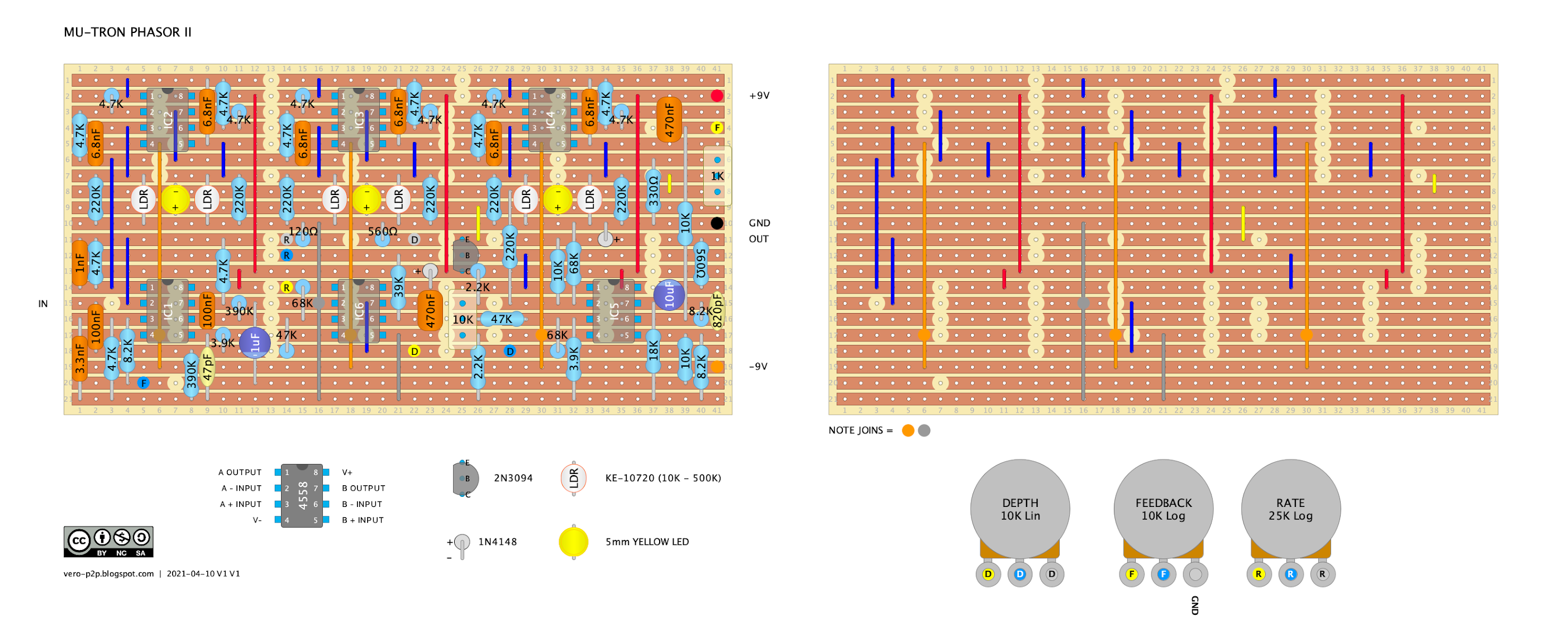
MUSITRONICS: Mu-Tron Phasor II

A classic phaser from the mid-seventies - the Musitronics Mu-Tron Phasor II.  It has the same six-stage phaser as the Bi-Phase, with less happening in the oscillator section.  

This is the hardest layout I have ever done and took some time to finish and check...  including some time wasted after I started using a layout with errors in the oscillator section, which was very annoying.   

Being a six-stage phaser using DIY vactrols - what could possibly go wrong?  Unverified at present / build at your peril.

This should just fit in a Hammond 1590BB enclosure (landscape),  The dual rail power supply will need to be done on a separate board.  

I have not wired as per the original, as it was not true-bypass, and it has a relatively low input impedance of 390k.  If you really want to wire it up as the original, just check an old schematic, and you should be able to modify a layout to accomplish this.  


MU-TRON PHASOR II - VERO LAYOUT

MU-TRON PHASOR II - GUITAR EFFECT VERO LAYOUT


Pedal PCB values/schematic were used for the layout above, which is slightly different to one of the original schematics that I've seen.  This is running at +/- 9v.


MU-TRON PHASOR II - VERO LAYOUT - LFO WAVE SHAPE MOD

After looking in awe at the Mu-Tron Bi-Phase schematic, I realised that most of it are actually the same, or at least quite similar to the Phase II.

The mod below adds a sone / square wave selector.  I'm surprised they never included this on the original, as it's pretty easy to add (bearing in mind that this is currently an unverified layout).


MU-TRON PHASOR II - VERO LAYOUT V2


This layout is based on an original schematic, it's running at +/-12v, and it has very minor differences here and there - mainly in the LFO.  

MU-TRON PHASOR II - CALIBRATION

Note this refers to the older AC-powered unit, which is the layout directly above - please don't connect anything to mains power, or you may die in the process.  

In the instructions, it mentions changing R37 from 68k to 82k if there are flat spots on the waveform.  R37 is the resistor from Depth 2, connecting to pin 3 of IC5.  


MU-TRON PHASOR II VS BI-PHASE

A quick note on the main differences between the Bi-Phase and the Phasor II, as they are actually very closely related.  For starters, there are two phasers in the Bi-Phase - obviously.

Common
  • The six-stage phaser
  • The input section is basically the same, along with the feedback control
  • LFO oscillators have the same basic topology in terms of waveform generation
  • Sweep, Rate and Depth controls

Bi-Phase, Main Differences
  • LFOs have sine and square waves
  • LFO A rate can be controlled by an expression pedal
  • LFO B can be inverted or synced to LFO A
  • Additional routing controls, cause there are two phasers to play with - as an example, route Phaser A into Phaser B, giving a 12-stage phaser... 
  • Switching between Phaser A & B is controlled by a vactrol in the signal path of the output stage (audio section).  i.e. an optical switch.  When engaged, the switches increase resistance in the signal path to the point where audio does not pass.