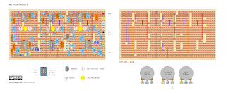
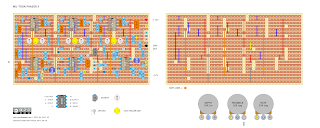
A classic phaser from the mid-seventies - the Musitronics Mu-Tron Phasor II. It has the same six-stage phaser as the Bi-Phase, with less happening in the oscillator section.
This is the hardest layout I have ever done and took some time to finish and check... including some time wasted after I started using a layout with errors in the oscillator section, which was very annoying.
Being a six-stage phaser using DIY vactrols - what could possibly go wrong? Unverified at present / build at your peril.
This should just fit in a Hammond 1590BB enclosure (landscape), The dual rail power supply will need to be done on a separate board.
I have not wired as per the original, as it was not true-bypass, and it has a relatively low input impedance of 390k. If you really want to wire it up as the original, just check an old schematic, and you should be able to modify a layout to accomplish this.
MU-TRON PHASOR II - VERO LAYOUT
MU-TRON PHASOR II - VERO LAYOUT - LFO WAVE SHAPE MOD
MU-TRON PHASOR II - VERO LAYOUT V2
MU-TRON PHASOR II - CALIBRATION
MU-TRON PHASOR II VS BI-PHASE
- The six-stage phaser
- The input section is basically the same, along with the feedback control
- LFO oscillators have the same basic topology in terms of waveform generation
- Sweep, Rate and Depth controls
- LFOs have sine and square waves
- LFO A rate can be controlled by an expression pedal
- LFO B can be inverted or synced to LFO A
- Additional routing controls, cause there are two phasers to play with - as an example, route Phaser A into Phaser B, giving a 12-stage phaser...
- Switching between Phaser A & B is controlled by a vactrol in the signal path of the output stage (audio section). i.e. an optical switch. When engaged, the switches increase resistance in the signal path to the point where audio does not pass.


No comments:
Post a Comment