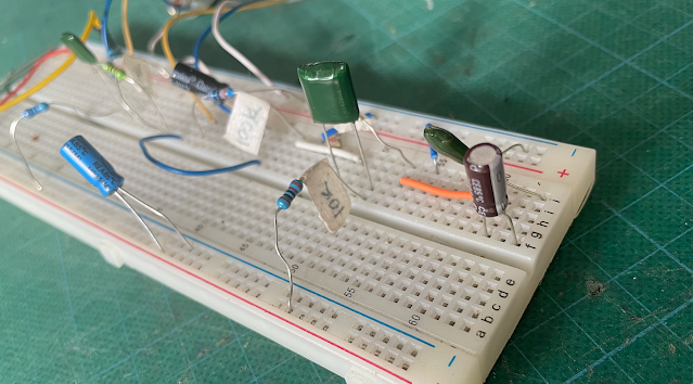
Breadboards are one of the most effective learning tools when it comes to electronics. Not only are they great for prototyping and testing circuits, but they also offer a hands-on way to fine-tune and troubleshoot designs—perfect for testing guitar pedals.
In this post, I’ll walk you through how I use a breadboard. While this approach may not be for everyone, it’s a method that’s worked well for me, and it could help you get more comfortable with circuit building.
HOW TO USE A BREADBOARD (For Guitar Pedals & Electronics Beginners)
So, where to begin? You will need:
- a breadboard
- power supply - bench top, battery or pedal power supply will do
- components to play with
- jumpers, which can be solid core wire, or you may have a bunch supplied with the breadboard
- input / output jacks, ideally with an on/off switch, or better yet a test box
PLANNING TO BREADBOARD A PEDAL
I don’t typically pre-plan my breadboard layouts. I’ll take a quick look at the schematic and then dive right in. Early on, I tried using DIYLC (software for creating vero layouts) to map out my builds, but I found that breadboarding is a hands-on, three-dimensional process. Once I started placing components on the board, my plans usually went out the window—so I’ve learned to just dive in and adjust as needed.
SO HOW DO THEY WORK?
Breadboards are relatively simple. They consist of rows and columns of holes that are electrically connected in a grid pattern. Along the edges of the board, there are vertical power rails—one for positive voltage and one for ground. You can buy fancier breadboards with additional features, but they all work in roughly the same way: you place your components and make connections using jumpers.
COMPONENT PLACEMENT ON THE BREADBOARD
When I build a circuit on a breadboard, I aim for a logical, linear layout. I don’t try to make the circuit as compact as possible. Instead, I leave a little bit of space between components to allow for easy adjustments and troubleshooting. Generally if you're breadboarding, you will be swapping components in and out and this means leaving room for clumsy fingers.
For simple circuits, the main goal is making sure everything fits on the board and is properly connected. Once you get into more complex builds, you might need to think about space a bit more, but for testing pedals, spaciousness is often your friend.
TESTING THE CIRCUIT
Usually I feed the circuit a sine wave from my signal generator and test that it's working as expected on one of my scopes. You could easily use an audio probe to do this as well.
For larger or more complicated circuits, I test as I build, making sure that each stage works.
After it's confirmed to behave as expected, I usually plug in a guitar and run it to my amplifier, as real world testing is the always the best. Just need to be a little cautious here - I have an amp that I'm not attached to for this purpose. I've never killed an amp in testing, but there's always a chance right? There is often a bit of popping and unsettling noises when touching parts on the board - just be aware of this.
When testing, I usually have a selection of parts to swap in and out to see how they effect the sound - in some cases I'll use a pot instead of a fixed resistor to sweep values. When I find a setting that I like, I'll take the pot out of the circuit to measure the value and replace it with the nearest value fixed resistor.
For transistors and caps, it's just a case of swap them and see what happens.
I usually have a few pots sitting in the parts draw with solid core wires soldered on for breadboarding. It's handy to be able to swap a few around to see what works better for you in the circuit.
TROUBLESHOOTING
OK - you've put all your parts on the breadboard and it looks fine, but it doesn't work. What next? Same as testing a regular circuit, check your voltages and probe the circuit to see where you went wrong.
It's often a component leg in the wrong hole, or a possibly a poor connection somewhere. Poor connections can be a thing with cheap or dusty boards, quite often on the power or ground rails. I normally tap and wobble parts to see if they make noises, maybe reseat transistors. In short, if it doesn't feel secure, it probably isn't a good connection. Although this could also be a sign that I need to spend more on my breadboards instead of getting cheap ones for a few dollars from China...
PRE-BUILD TESTING
In some cases I breadboard the entire circuit that I plan on making on a breadboard first, using the components that will be used in the final build. This is usually only for circuits that I know will be tricky to tune. Example: a MKI Tone Bender. In some cases I’ll just use the breadboard to test the transistors and not worry about the rest of the circuit.
OPTIONAL: COMPONENT LABELS
If you're like me and don't have the best eyesight, small masking tape labels on the legs of components is sometimes helpful. Especially when you start pulling out small metal film resistors and leaving them all over the bench.
I can read 4 band, 1w carbon films easy enough, 1/4w metal film is a tad tricky for me. Sometimes I avoid using 1/4w metal film for this reason. Same can be said for some caps - greenies are sometimes hard to read. I sometimes write the value on with a marking pen.


2 comments:
Thanks for this Andy, very useful info!!
Too easy - I'll have to add a few photos so people can see how shabby my set-up is.
Post a Comment