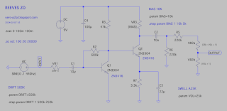
I saw this on the Gray Bench Electronics youtube channel, and given the cost and apparent popularity of Reeves pedals, I thought I'd post a layout. The schematic is also on screen for a lengthly period of time.
In depth explanation provided at Gray Bench, but in short, it's a silicon two transistor Zonk II with mods. There were multiple versions of the Zonk II back in the sixties, with distinctly different circuits - just scroll through the page on fuzzboxes.org to see what I mean.
Be sure to read the comments on this post, as there is some valuable info regarding changes / updates to the circuit - and like almost any simple fuzz, get it on a breadboard and have some fun with it before committing it to a board.
REEVES ELECTRO ZO - VERO LAYOUT
I added a polarity protection diode to the circuit, cause why not when there's room.
ZO NOTES
- the 10k bias pot is sometimes replaced with a fixed resistor
- the 470pf cap is not always present (value is potentially much smaller - 47pf)
- and read the rest on youtube...
ZO x ZONK II
Just a quick reference to the schematics - the Reeves schem is redrawn from the Gray Bench video & the silicon Zonk II is from all the usual places - but with the addition of the pulldown resistor that's visible in vintage units, but missing from a lot of schematics.
As you can see, they share the same bones, but with a few key differences. Notice the output cap differences - the Zo rolls off a bit more bass than the Zonk, and with the 470pf cap, a bit of treble goes missing too (apparently not all Zos have this cap, and it may be much smaller).
They both should have a decent amount of output, bit the Zo should have more than the Zonk by a fair margin.
Spice did not have the right silicon transistors, so I just used the plain old 2N390X in each one for a fair comparison between an NPN & PNP circuit.


13 comments:
The 10nF is not connected correctly and the Drift is pretty subtle at any mid to high volume level.
Thanks Markie - layout corrected. Maybe try a larger pot if the Drift isn't doing as much as you'd like it to.
Got this from Dirtbox Layouts: "*Update 240203* Reeves Electro got in touch with Gray Bench since two of the pot values was incorrect in the trace." According to that the pot values are: Drift 500KB, Texture/Bias 10KB, Volume/Swell 25KB. Also a 1M resistor was added between input and ground.
Thanks for the heads-up Jukka
Thanks so much for your nicely laid out Vero, works great! Having the Bias and Drift pot wires placed on adjacent rows enabled me to solder JST-XH connectors on the stripboard, with cables then going to the pots. This made it so much easier to put everything together compactly, yet still allow easy board removal for troubleshooting and/or swapping transistors.
No problem - I'm glad my minor case of wiring / vero OCD helped out
Great thread what Rated Voltage are all the capacitors being used in the ZO x ZONK II? I'm also wondering about the LED its voltage etc and is that a resistor (size) between the switch and LED - any guidance on that would be great - thank you.
Hello
CAP VOLTAGE: I'm not sure what was used on the original, but being a 9v circuit, most people would aim for caps rated at over 20v (at least double the circuit voltage).
LED RESISTOR / VOLTAGE: 4.7k is really common, I tend to use 5.1k as I prefer less brightness. Just look for a standard 3mm or 5mm LED.
Voltage is usually left off the datasheets, they list power dissapation instead. I've never managed to mistakenly buy the 'wrong' LED, you should be fine. If you see voltage mentioned, it's usually forward voltage, which relates to the LED as a diode. Ignore this, as it will be low, probably 2.5v.
There is also a comment on dirtbox layouts by Markus suggesting the 470pf is 10x too big….. finally I have noticed in his latest build there is a second ceramic cap. Unsure of the value .
thanks for that ... i dont have a schem for this one hahah (no really) =}
each batch i use slightly different HFEs (out of necessity, i didnt have many cans left) so i tuned them per batch, these caps are part of getting them close to my control build =] New transistors now and i have 1lb of them so this is a thing of the past anyhow
as of the facelift version with new transistors (2n2926) the output pot is 100k
thank you - very kind of you to drop by and add a few comments / advice
Post a Comment