He used to be a designer for Gallien-Krueger (I think, something like that anyway), so he has some idea as to what he's doing.
There's not much out there in terms of diode based compression, without getting into expensive studio or vintage gear, so this is kind of unique in that sense - it's not another Orange Squeezer in a different wrapper, and for me at least, I think it has a different sound and feel to an optical compressor (which I also quite like).
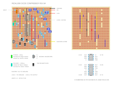
This was made using the narrow layout, but with a few extra rows added either side to allow for proper mounting.
JONNY RECKLESS DIODE COMPRESSOR - VERO LAYOUT
Slightly smaller vero layout - unverified, as I have not built it. It should work, as it's a variation on the one above, which I have built.


11 comments:
Hi! Is it possible to add a external blend circuit to this design??
Hello. Probably best to ask that question here on the DIY stompboxes thread. https://www.diystompboxes.com/smfforum/index.php?topic=120686.20 I'm sure it would be possible, but probably not straightforward and of course I'd need to do another layout for it.
Hi Andy! how are you? I built this compressor again but with the 3rd layout the smallest one, it works but I have a little but noticeable distortion and with the compression maxed out it distorts like an OD.
I am using Tl074 (tried op4134 too) and a lm1458, I think I bought bad quality TL072's, I tried various OpAmps and this was the best. For the transistors I used 2n5088, I also tried with 2n2222a and bc547b.
I noticed that the second layout does not have the 100nf caps and the third one (the one I made) has only one, I don't know if it will be important. I triple-check, I think everything is fine also tested with DMM.
Any idea what it could be?
PS: The first one I built I gave it to my pal... now I regret it🤦♂️
Hello - I’ll check the small layout again and get back to you. The 100n ceramics were additional power filtering, so should not cause that result.
Thanks Andy!
I’m so stupid at times I wonder how I put my shoes on in the morning.
I checked the layout for errors - twice…. only to realise that photo directly below it was a pedal that I built using the layout you’re having trouble with. In my defence, I am slightly hungover.
Anyways, not sure what is happening with your build. What are your voltages looking like?
Hahahaha yeah I know that feeling 🤣... Here are my voltages:
IC1
1. 4.28
2. 4.28
3. 3.85
4. 0
5. 5.74
6. 5.74
7. 5.72
8. 8.67
IC2
1. 4.78
2. 4.32
3. 4.32
4. 8.65
5. 3.80
6. 5.57
7.3.82
8. 4.47
9. 4.28
10. 4.28
11. 0
12. 4.30
13. 4.30
14. 4.33
Q1
C 8.44
B 4.30
E 3.71
Q2
C 5.40
B 4.23
E 3.63
I'll check the voltages on mine and get back to you.
I unpublished the MKIII post, as I can't find the layout file to correct it. The MKIII is very forgiving when it comes to transistors. Low gain for the darlington pair, and almost anything works in Q3. Q3 is where most of the action happens. I remember soviet transistors as having a slightly harsher / more aggressive tone about them.
I prefer the smaller bias resistors - hard to describe the difference - it just feels better to me.
Instead of the blend pot for the treble caps that I had in the old layout, I'd put them on a switch. The 2n2 is as small as you'd want to go, 4n7 is my preferred size, 3n3 is also pretty nice.
Your voltages are very close to mine - so I think all good on that front.
I’d check resistor values for the opamp in the audio path feeding the diodes and the resistors on the pair of transistors. Maybe you picked up a wrong value and gain is set wrong
While you’re at it, maybe double check cuts around that area and diode polarity.
Someone said to me once "I wonder how I put my shoes on in the morning..." You wont believe me but I had sustain 1&2 lugs connected to 9v instead of ground🤦♂️🤦♂️🤦♂️... Thanks so much for all of your, sorry for wasting your time.
All good - never a waste of time. I'm glad you found the problem and it was an easy fix. People that pretend to never make mistakes, or never admit to them scare me.
Post a Comment