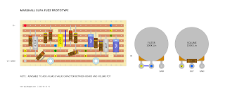
This is the early version of the Marshall SupaFuzz based on a Tone Bender MKI - it's close to the original layout used.
Strangely it never had a coupling cap on the output, so best to add something decent sized there. I've also seen a couple of photos with a power cap across V+ / V- I couldn't see a value, but on an old pedal like this I would expect maybe a 25uf or 50uf - running of battery this is not exactly essential either.
Transistors are OC75, but use whatever you can get with decent amounts of leakage and moderate hfe, which is typical of OC75s.
Being a Tone Bender MKI variant, you can easily add a fuzz pot. In this circuit the 470k resistor and the 47k resistor bias the base of Q2 (the middle one).
The 47k resistor from the base of Q2 to ground, is normally where the fuzz pot sits in a MKI circuit. Just check the standard Sola Sound Tone Bender MKI to see how this works - pretty easy to convert if you want to try this. Alternatively, one could use a trimmer instead of the 47k resistor to dial it in and leave it set in a happy place. This might be the best option.
Unlike the other Marshall Supa Fuzz, the filter control here is actually a filter control...


4 comments:
Verified and sounds great. Actually very close to Led Zeppelin I which surprised me a bit. Or lets say you can get the sound in some positions. Maybe I play with the layout a bit as I would love it to be more agressive like the Gary Hurst MKI.
Btw your advice for using a trimmer instead of the 47k resistor was brilliant. I could easily find the position I liked. Thank you!
Regarding the power cap across V+ / V-, I think the value is 25u.
https://www.flickr.com/photos/195631300@N04/52727931893/in/album-72177720306489583/
…and something else, isn't the 10n on the right going to the bottom row. It looks like it on the pictures:
https://www.flickr.com/photos/195631300@N04/52076574635/in/album-72177720298975174/
https://www.flickr.com/photos/195631300@N04/52727710064/in/album-72177720306489583/
Hello - the two bottom rows are linked with a jumper. Both are ground.
Yes, in the photo it's definitely going to the bottom row with the jumper sitting next to it / underneath it
Post a Comment