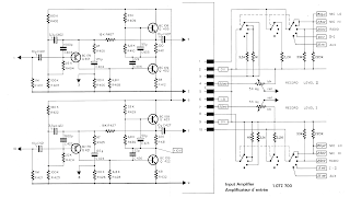
This is the input amplifier from a Revox A77 reel to reel (circa ~ 1967) - which also happens to be almost identical to the mic preamp in Trident A-Range mixing consoles from the early seventies.
So far out of the preamps that I've been working on, which is the Neve, RCA and this, I'm happiest with this one. Apart from sounding cool, it also retains a pretty flat response, and could be used as an "always on" sweetener. I was probably just hearing very light distortion, but I did prefer the tone of my guitar with this on running clean, rather than off. It felt a bit more forward and bigger sounding.
It’s very very loud - tons of output level available. This could happily be described as a clean boost as well as an overdrive / light fuzz.
Due to the insanely high output, I think this is a good candidate for some form of High or low pass filter for some tone shaping. If you’re using it to smash another pedal or front end of an amp, some bass cut might be handy. Note that on the highest gain setting (which is fuzzy), it does roll-off high and low frequencies.
The original uses silicon transistors, I've used Japanese 2SD128 germanium transistors, which are usually around 40hfe.
REVOX A77 INPUT AMPLIFIER SCHEMATIC
TRIDENT MIC PREAMP SECTION FOR COMPARISION
The output is very high, and the overdrive / fuzz does not occur until the last couple of hundred ohms when resistance to ground is heading towards zero (hence the reverse log pot)
my notes from spice re the schematic above: - input cap can be 1u without effect response
- 1u output cap only has slight low frequency roll-off, even with a 5k volume pot
- decrease C4 to 10u to roll-off low frequencies
- increase C2 to increase high frequencies
- decrease R8 to reduce fuzz
- C6 can be smaller (down to 10u)
- C5 can be removed, or increased to boost treble from 8k / 10k
- R5 can be removed for a very slight gain boost
There are so many variables, I haven't show the LTspice results here, or it would be a very lengthy post.
- input cap can be 1u without effect response
- 1u output cap only has slight low frequency roll-off, even with a 5k volume pot
- decrease C4 to 10u to roll-off low frequencies
- increase C2 to increase high frequencies
- decrease R8 to reduce fuzz
- C6 can be smaller (down to 10u)
- C5 can be removed, or increased to boost treble from 8k / 10k
- R5 can be removed for a very slight gain boost
REVOX A77 INPUT AMPLIFIER - CLEAN BOOST / OVERDRIVE / LIGHT FUZZ
Work in progress on the bench - as you can see, it's the mojo layout (also know as the unnecessarily large version). Approx 65mm x 40mm on 0.15" vero with 1w carbon film resistors


11 comments:
Do you happen to remember the gain range of the Ge transistors you used? I'd like to give a Ge version a shot, but most of my NPNs are lower hFE. If it works better with higher hFE Ge's, maybe I'll try a Sziklai or Darlington pair.
I've got a Si version of this on the breadboard at the moment and did some digging to find the bins & hFE specs of the original transistors for reference:
- Q1 BC179B hFE: 240-500 (Low-Noise)
- Q2 BC108B hFE: 200-450
- Q3 BC109C hFE: 420-800 (Low-Noise)
Hello. I used 2SD128 transistors, typically about 40hfe.
Hi. I made the revox A77 input preamp into stompbox.
I wanted to follow your schematic . But I don't have any GE trs.
So I decided to follow the original schematic.
I used lt1054 and zener to make 21VDC.
I used a spst(on/off) potentiometer as boost pot.
I was satisfied with the result.
Thank you for introducing interesting circuits.
Great - that must have a lot of output running at a higher voltage.
Yes it is. It is really loud. But I can adjust it with volume knob. So it is okay.
Hello, interesting article. I use a revox a77 solely as preamp for my CD player and sounds so much better, not sure what it does but the soundstage is so open when is engaged. I wondering if there is a stereo version of your pedal would do similar effect.
I replaced the silicon transistors with germanium ones and may have made some other minor tweaks (it has been a while since I looked at this). The original probably works off higher rail voltages as well.
With this in mind, I would not expect it to work the same.
Thanks, do you think is possible to replicate the original stereo preamp of the a77 on a small box with the higher voltages?
Yes, that could be done
Is this something you could guide me on, I have some electronics basic experience...
Sorry, not at the moment. But I will get you started.
Run it at 24v. Use silicon transistors, and remove the fuzz pot. You could probbaly work it out yourself, as the information is all here.
Post a Comment