I'm a bit of a fan of some of the late sixties / early seventies Beatles fuzz sounds, so I was interested to see this pop-up. Like the Creepy Fingers Lonely Hearts Fuzz, it's based on the fuzz section built into the Vox UL series amps. I'm feeling a bit of déjà vu posting this, as it is very similar to the Creepy Fingers - keen to give it a try anyway.
Aclam are of course best known for their Doctor Robert, which is the normal channel of the UL. I guess by releasing the Mocker, they're completing the family.
Schematic can be found here on PedalPCB.
ACLAM MOCKER - VERO LAYOUT
If you don't have BC547A transistors, just use something low-gain. A 2N3094 will probably do just fine. Same for the clipping diodes, just use whatever silicon diodes you have handy - the PedalPCB schematic listed voltages at about 0.6v, which is pretty standard for silicon. Without trying them, it's hard to say what mojo the OA200 diodes provided (if any).
MOCKER VIDEO DEMO
ACLAM MOCKER ON LTSPICE
I noticed that Aclam has left the pair of bias resistors for Q2 quite small - close to the original. On similar adaptations of this circuit, they're often increased to more familiar values. Jext Telez has 20k/22k the Creepy Fingers uses 68k/47k
Trace taken at the Q2 collector - the signal is pretty dirty before it hits the clipping diodes (with sweep on the bias control)
The diodes flatten things out a little and reduce the overall level slightly - apart from a bit of filtering with the tone control, not much else happens to the signal, as the last stage is a buffer
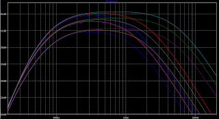
The frequency response is as expected, nothing unusual going on here - slight mid-hump on some settings, tops rolled off.
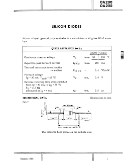
DATASHEET FOR OA200 DIODES
Aclam used some vintage silicon diodes - here's the original datasheet. I wouldn't feel too bad if you just dropped in some modern diodes with a vaguely similar spec.


6 comments:
Do you have this one made? I replaced OA200 with 1n4148, and the sound is very good.
Hi Ding. No, I have not made this one yet. Most silicon diodes sound quite similar to one another - it probably sounds the same as the OA200.
Thanks for the feedback
In the circuit diagram on the PedalPCB, why do the signals enter through the negative terminals of C1 and C8 capacitors, is it due to the lower input signal voltage?
Hi Ding,
Normally when a polarised electrolytic capacitor is used in a circuit, the positive side has higher potential than the negative. Keep in mind that it's letting AC signal through, while blocking DC. There's more DC on the base of Q1 than there is on the input. Q2 has more on the collector of Q2 than the base of Q3.
In extreme cases, damage will occur to the capacitor if it's placed the wrong way around. example: place an electrolytic the wrong way across power rails and they can pop/explode.
Thank you for your explanation. When I make pedals, I often replace them with non-polarizing capacitors in such situations. Now I have finally learned it.
I try and replace electrolytic capacitors with film capacitors where possible, as they have a much longer life and very little leakage.
Some people also use multilayer ceramic capacitors (MLCC) as they're available in larger values.
Post a Comment