Wednesday, December 29, 2021

BOSS: FZ-3 Fuzz

Initially I wasn't sure about doing a layout for the Boss FZ-3, as it isn't the most popular fuzz out there - then looking at the schematic, it appears to be quite tweakable, so I thought why not make a start, and see where this goes.   

It has elements of a Tone Bender, a silicon Fuzz Face at its core, with a BMP type tone control.  Boss when next level on power filtering with this one too.


Details here on Aion FX.


BOSS FZ-3 FUZZ VERO LAYOUT

BOSS FZ-3 FUZZ VERO LAYOUT


FZ-3 VIDEO DEMO


Sunday, December 12, 2021

GUITAR: Tokai, Love Rock LS260, Made in Japan, 2011

I haven't posted in a while, as I've been selling a few things, and doing a bit of guitar shopping at the same time, which has taken up way more of my time than expected.

A Yamaha SL500 or an Aria Pro II Leopard were looking promising at one stage, as I was looking around for a vintage Japanese Les Paul, and then I saw a Tokai Love Rock from the premium range appear second-hand for a decent price...  slight change of plan and budget. 

It's a 59-spec Les Paul, and it feels and sounds great.  I wasn't sure about the Seymour Duncan Phat Cat P90-style pickups the previous owner had installed, but they sound good.  The previous owner was selling the Love Rock as he's a Fender guy and could never get used to the neck profile. 

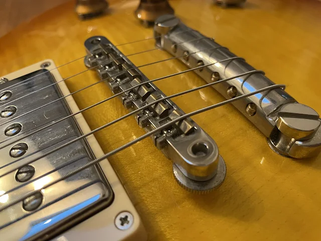
 TOKAI LS260 LOVE ROCK - MADE IN JAPAN, 2011

TOKAI LOVE ROCK LS260 - 2011, MADE IN JAPAN 


HOW DOES THE LOVE ROCK SOUND?

It's often difficult to describe sound, but I'll give it a go.   Acoustically it sounds really nice - loud and clear, good note articulation - one of the best solid body electrics I've ever heard acoustically. 

The neck pickup has a nice rounded tone, enough bass to make me happy but not enough to get muddy, and it's not too bright either.  The bridge pickup has a good focused midrange bite, but it's not too hard on the ears.  A bridge pickup that I can live with is usually a sign of a decent set of pickups to me, as I generally prefer the neck.  

And of course, a 59 Les Paul is famous for sustain - who better to describe it than Nigel from Spinal Tap.


LOVE ROCK LS260 BUILD QUALITY

It's pretty much flawless, from what I can see. The action is low, and the fretwork is excellent.  

The neck profile is on the slightly larger side of things compared to some modern necks, but still very comfortable.  I like it.

Electronics and hardware are all great.  The cavity is insulated.  

It's one of the few guitars that I've bought where I don't feel like I need to change anything or tweak it for better playability. 


IS THE TOKAI LOVE ROXK BETTER THAN A GIBSON LES PAUL?

The age-old question/debate for a high-end Japanese Les Paul - is it better than a Gibson?  It's definitely better than a Gibson that I recently played, but I've never actually picked up a 1959 Les Paul.  So better than some, yes, better than all, probably not.  For the money I paid, there's no question that it's better value, as long as you're OK with a guitar called "Love Rock".   


TOKAI LOVE ROCK LS260 SPECIFICATIONS - 2011, MADE IN JAPAN

  • Two piece Maple top - looks like a honey burst
  • One piece Mahogany back
  • One-piece Mahogany neck
  • Rosewood fretboard, 12-inch radius
  • 22 frets
  • Switchcraft switch and jack
  • CTS pots
  • Sprague black beauty capacitors - which are gigantic...  and completely pointless as a cap is a cap…. I’ve seen a few different options in higher-end Tokai’s, so I guess someone thinks this is a selling point. 
  • PAF Vintage MKII hum buckers are stock - this one had Seymour Duncan Phat Cats installed (it did come with the original pickups in the case)
  • Pickguards are installed upon request, which is nice - no holes in the guitar if you prefer not to have one
  • Not sure about the weight - it's not light, that's for sure


TOKAI LOVE ROCK LS260 - 2011, MADE IN JAPAN

TOKAI LOVE ROCK LS260 - 2011, MADE IN JAPAN

TOKAI LOVE ROCK LS260 - 2011, MADE IN JAPAN

TOKAI LOVE ROCK LS260 - 2011, MADE IN JAPAN


TOKAI LOVE ROCK LS260 - 2011, MADE IN JAPAN

TOKAI LOVE ROCK LS260 - 2011, MADE IN JAPAN

TOKAI LOVE ROCK LS260 - 2011, MADE IN JAPAN

TOKAI LOVE ROCK LS260 - 2011, MADE IN JAPAN

TOKAI LOVE ROCK LS260 - 2011, MADE IN JAPAN

TOKAI LOVE ROCK LS260 - 2011, MADE IN JAPAN

TOKAI LOVE ROCK LS260 - 2011, MADE IN JAPAN


TOKAI LOVE ROCK LS 260 VIDEO DEMO


Wednesday, November 24, 2021

VERO: How to Mount Vero in Pedal Enclosures

THE PROBLEM WITH VERO / STRIPBOARD LAYOUTS

As much as I like a bit of vero (clearly), vero is not meant for commercial-scale production, at least in the modern sense.  Unlike PCBs, where pots and switches can all be mounted on the board, thus providing a convenient way to hold the board in the enclosure, vero layouts are almost never designed this way.  This brings us to the issue at hand - I've built it, now how do I make it stay put in the box, or how do I know this thing will be reliable?

Vero, or stripboard layouts are often laid out by folks like me, with small size often being the main driver of the layout, without any consideration for anything else.  What is rarely seen on layouts is space for mounting points, or any indication of how it should be laid out in an enclosure with pots, jacks, switches etc.  Sure, we all like to do our own thing, but it's kind of hard to work out when you're just starting out.  I know when I was starting out, boards were jammed in enclosures in any way possible, usually with a lot of excess wire.  As long as it worked and I could close the lid, I was happy.


SO WHAT TO DO?

Well, kind of obvious - secure the vero board to the enclosure properly.  The board is literally full of things that you don’t want touching the enclosure, switches or any other conductors.


HOW TO MOUNT VERO IN A GUITAR PEDAL ENCLOSURE?

Standoffs

This is my preferred method.  Self-adhesive plastic standoffs are pretty handy - but you will need to check if there's space on the layout for a few holes and that there is enough room in the enclosure once the pots and switches are in (which should happen first, in my opinion).  If there isn't enough room, see if there's room to add a couple of rows or columns to the vero layout for mounting holes.

Standoffs come in many different shapes and sizes, usually with a plastic snap to lock them in place, or a small screw.  Naturally, if you are using the metal screw type, make sure that the screw isn't shorting the conductive strips on the vero board.   Of course, there is the bulletproof method, of screwing the standoff all the way through the enclosure, but this is a little harder to do and can limit space for graphics on the front.


circuit standoff - stomp box / vero board mounting


circuit standoff - stomp box / guitar fx / vero board mounting

This is a small point-to-point board - a single screw was enough to secure it.  In retrospect, I should have used two.  


circuit standoff - stomp box / guitar fx / vero board mounting


circuit standoff - stomp box / guitar fx / vero board mounting

Plastic standoffs on each end of a D*A*M Fuzzsound worked well


Glue

Quite a few people use hot glue guns to secure boards, and it works, but good luck if it ever needs repair.


Tape & Velcro

Thick double-sided tape and velcro also does the job.  At least with Velcro, you can remove it for repair, but something about velcro in a pedal bothers me.


Gum

No not that type of gum.  This is a suggestion from a comment left on the post (thanks Brain).   There's a sticky gum/gel specifically designed for sticking down boards, but you can still remove them later (with a bit of effort).

https://guitarpcb.com/product/gum-wadz-pcb-mount/   


LAYOUT PLANNING

I normally look at the vero layout, pots, switches and enclosure size before starting the build.  This way I can get a feeling for how I might finish, before I start.  Kind of frustrating to have something in mind, only to find that it was never going to fit after building the circuit.  I learnt this the hard way, maybe more times than I care to admit.

After I've built and tested the circuit (with ample wiring already on the board), I double-check that everything fits, by first adding the jacks, switches and pots to the finished enclosure.  Then drop the board in, to confirm the initial plans are still valid.  

I usually wire up the jacks, stomp switch and LED first - then I attach the circuit to the enclosure, and cut the cable to size, and solder connections as required.

Another method I sometimes use is to create a cardboard wiring jig, and do most of the work there, before transferring to the proper enclosure.   This just provides a bit more room to move, as some enclosures can be a little cramped to work in, and it works out about the same in terms of final product.


How bad does the cardboard jig look?   This is the Revox A77 preamp that I put in a wedge enclosure.


WHAT TO AVOID WHEN MOUNTING CIRCUITS IN PEDAL ENCLOSURES?

Now I think I've done nearly all of these things at one stage - so no judgement if you have too.

Try not to:

  • Wrap it in electrical tape, sure it works, but what a mess
  • Stick it in a plastic component bag
  • Do nothing and hope for the best / won't the wires just hold it where it should be?


Sunday, November 21, 2021

MAD PROFESSOR: Stone Grey Distortion

Another CMOS based distortion, this time from Mad Professor - the Stone Grey Distortion.  Details available on Aion FX, including schematic.  

Not that the original uses JFETS acting as diodes for clipping, which means very little if any difference when compared to a regular diode.  If you want to use JFETS, details are in the Aion build documentation - and there's room for it on the layout.  I initially started with JFETS on the layout, but if a 1N914 does the same thing...  


MAD PROFESSOR STONE GREY DISTORTION - VERO LAYOUT

MAD PROFESSOR STONE GREY DISTORTION - STOMPBOX VERO LAYOUT


According to the internet, the Stone Grey Distortion is based on this circuit from an old Japanese electronics book.  The first iteration was by Bjorn Juhl of BJFe called the Cliff Hanger, before if was licensed to Mad Professor.


Saturday, November 20, 2021

ELECTRO-HARMONIX: Hot Tubes

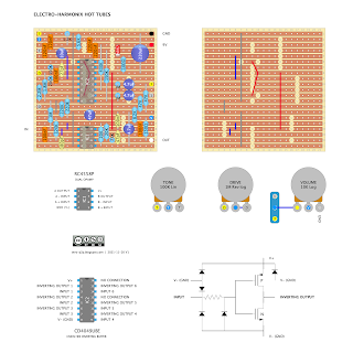
This is the CMOS version of the Electro-Harmonix Hot Tubes from the late seventies.  I used the Aion FX schematic, which has some minor differences to the original.  Smaller Drive pot, as it's difficult to source pots over 1meg, and some improved power protection and filtering.


ELECTRO-HARMONIX HOT TUBES - VERO LAYOUT

ELECTRO-HARMONIX HOT TUBES - GUITAR EFFECT VERO LAYOUT


HOT TUBES VIDEO DEMO


Wednesday, November 17, 2021

PETE CORNISH: TB-83 Treble Booster, Point to Point Layout

I followed a vaguely similar layout to the one pictured at the bottom of the post for the Pete Cornish TB-83 Treble Booster.   

This is a straight treble boost using a silicon transistor - it's going to sound horrible into anything apart from a cranked valve amp, or maybe a valve based pedal.  Given this was in Brian May's rig, think normal channel of a cranked AC30, with this hitting it.  Well maybe you aren't running nine AC30s at once, all running so hard the border on catching fire, but you get the idea.


PETE CORNISH TB-83   POINT TO POINT LAYOUT

PETE CORNISH TB-83 - POINT TO POINT LAYOUT


PETE CORNISH TB-83 - LTSPICE

I used the schematic from Fryer Guitars - link here.  

PETE CORNISH TB-83 - LTSPICE


Tuesday, November 16, 2021

GUILD: Brian May Box Treble Booster

The layout is from the Guild Brian May Box schematic, which is marked as designed by Pete Cornish, but he has disputed this at one stage.

There's a massive write up here on Fryer Guitars, including photos of inside Brian May's Pete Cornish built pedal board, and inside a pretty vintage looking Pete Cornish treble boost, which also happens to contain a buffer.  Given that Fryer rebuilt AC30's for Brian May, I think the man knows a thing or two.

Either way it's a buffered treble boost.  You can either wire this up as buffered, or true bypass, whatever you prefer. 


GUILD BRIAN MAY TREBLE BOOSTER - VERO LAYOUT

GUILD BRIAN MAY TREBLE BOOSTER VERO LAYOUT


GUILD BRIAN MAY TREBLE BOOSTER - ORIGINAL SCHEMATIC

GUILD BRIAN MAY TREBLE BOOSTER - SCHEMATIC


GUILD BRIAN MAY TREBLE BOOSTER - LTSPICE

Not much to see here.


And one difference to other treble boosters from the ringmaster family is the 10n input cap vs the standard 4.7n.   


Friday, November 12, 2021

VOX: BM1 Escort Transistor Practice / Busking Amp

I just bought this rather beat-up Vox BM1 Escort practice amp from the seventies, or maybe early eighties today.  I'm thinking seventies, as it doesn't have an IEC power connector, and the grill cloth is the red/brown colour. 

The back panel looks different to the one on Vox showroom and other photos that I've seen, so not sure what’s going on here - maybe it’s from a different production run or regional difference?  The rotary battery/power selector switch has been replaced with a standard toggle switch, and the volume pot doesn’t look original; apart from that, all working as it should.

My first thought on this one - it's a little monster.  Way louder than I thought it would be, and the driven sound is cool.  I really punished my ears testing this...  slightly regretting it now.  It seems to like running somewhere between half and three-quarters volume, with the tone in a similar position depending on the input used.  It's also pretty happy with the volume on full - it really fires off some attitude.  I think it would be interesting to record this little thing running hot.

Clean sounds? Can't say I spent much time in this area of the amp.

VOX BM1 ESCORT - SOLID STATE PRACTICE AMPLIFIER

  • One channel, two inputs.   Normal and Brilliant
  • Single tone and volume control
  • Battery or mains power switch
  • 5” Elac speaker (Elac were used in a lot of Vintage Vox amps, quite sought after)
  • Powered by a single TB810S IC amplifier
  • Output for extension cabinet
  • Manufactured from the mid-seventies to early eighties
  • The cabinet is approximately 33cm x 22cm x 13cm, and it probably only weighs a couple of kilos without a battery
  • Battery is a PP9 - 9v, 5aH, 6cm x 5.5cm x 8cm

The batteries are large, expensive and are reported to not last long, which I believe is why Vox created this version with the option to run off mains power.  As a busking amp, you would want to make money petty fast, as you would need to make $20 just to break even with the cost of the battery.


Vox escort guitar amplifier


VOX ESCORT SCHEMATIC

Vox escort guitar amplifier schematic

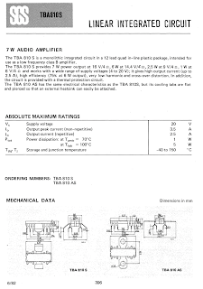
IC AMPLIFIER DATASHEET

I've seen the amp mentioned as being 3.5 watts, but I can't see this anywhere on the data sheet - looks like 2.5 watts when running at 9v.


Sunday, October 31, 2021

CORNISH: SS-3 Modded Diode-Compression Opamp

Details of this project can be found here - as I started with a modded Pete Cornish SS-2 using the Joe Davvisson diode-compression op-amp, and then moved on to this.  Essentially the same as the SS-2, but with the addition of a lo-cut.  

After a bit of testing, I’d suggest a C50k for the sustain pot, followed by B50k, and A50k if you have none of the previous.


CORNISH SS-3 WITH DIODE-COMPRESSION OP-AMP - VERO LAYOUT

CORNISH SS-3 MODDED WITH DIODE-COMPRESSION OPAMP - VERO LAYOUT


The layouts works - I added a buffer on top of this build.  

CORNISH SS-3 WITH DIODE-COMPRESSION OP-AMP - VERO LAYOUT BUILD PHOTO


Saturday, October 30, 2021

INTERFAX: Harmonic Percolator, Albini Values, 0.15" Vero Layouts

Since I've been on a bit of a Harmonic Percolator thing lately, I thought I might do some 0.15" mojo layouts using Albini / Mad Bean Pepper Spray values.


INTERFAX HARMONIC PERCOLATOR, ALBINI VALUES - VERO LAYOUTS


INTERFAX HARMONIC PERCOLATOR, ALBINI VALUES - VERO LAYOUTS

INTERFAX HARMONIC PERCOLATOR, ALBINI VALUES - VERO LAYOUTS

INTERFAX HARMONIC PERCOLATOR, ALBINI VALUES - VERO LAYOUTS