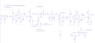
This is a Pete Cornish SS-2 using Joe Davisson's diode-compression op amp. It sounds pretty good - a lot like the regular SS-2, but without any distortion artifacts on sustained notes as it fades outs. It's also quieter in terms of noise. This one is getting boxed up, and now I want to try a SS-3 version.
For my ears it sounds best at 18v, and with a Cornish buffer in front. You can notice the buffer on cleaner sounds in particular, as the high frequencies are a little brighter. 18v sounds more open with better string clarity. 9v still sounds good, but it's more compressed and less dynamic in my opinion - may be a tad thicker sounding as a result of this, which some people may like.
Being based on the MXR Distortion +, higher gain settings roll off bass and treble to provide more of a mid-hump. It also sounds pretty good with the tone control wound all the way back. Low gain settings sound pretty nice too, as the frequency response flattens out.
The tone control is definitely needed as the treble can need a bit of smoothing out on some settings. It works well for a simple tone control.
I tested it on a transistor and valve amp - both had their own charms. Could not say which one I preferred. The valve amp liked it more when it was just breaking up, and then pushed with the SS-2 - but then again when doesn't a valve amp not like being pushed on breakup?
Things to tweak if you feel like playing around with the tone;
- C2 - definitely increase to 22n (input cap). 10n forms a 66hz HPF with R8, 22n forms 30hz HPF
- C8 - 10n capacitor paired with diodes to ground (forms a 1.5khz LPF with R11)
- C5 - 10n capacitor from clipping section into tone 3, rolls off some bass (I'm using a 22n here)
- C9 - 10n capacitor from tone 1 to ground
- Germanium Diodes: different combinations, types - usual diode mods...
- Reverse log gain pot like the SS-3


11 comments:
do the different coloured links have a specific significense, also how could i go about identifing a germanium diode, seeing as i use a lot of recycled parts, 70 year old noob
Hi Colin. On my vero layouts I colour code links. Red for power, dark grey for ground, and blue for signal. Orange is normally for bias voltage (not present on this layout). There is zero significance for any of the colours on the breadboard. I grabbed whatever was closest.
Germanium diodes are made from glass, and are usually a lot larger than modern silicon diodes. If you have a multimeter with a diode function to check forward voltage, it will be much lower than silicon, usually ~0.3v. Look closely, and one can often see a tiny wire inside.
You may have already heard this, best to avoid old electrolytic capacitors when using recycled parts. Unlike most other components, they can degrade over time.
PS. This is an untested work in progress. Do not make this or you may be disappointed with the results. It might be really good, I just don’t know yet.
hi Andy, thanks for your informative reply, much appreciated, i'm waiting for a good multimeter, as i fryed my previous one, fuse not with standing!
How did you cook your multimeter?
i was testing high voltage (240) and accidently switched to low voltage setting, i'm hoping for my daughter bring me a better meter nl Astro AI DM 6000 ar which according to reviews is excellent value for money, lots of features too
Yep, that will do it. The new one looks nice. If you are using a lot of recycled parts, the $20 multifunction testers on eBay are great for testing unknown transistors
on the cornish ss 2 layout i noticed the 1n4001 is reversed, please correct me if i'm wrong
Hello. That’s for polarity protection, sitting across v+ and v- It’s meant to be that way around. There’s another way to do it where power runs through the diode, in which case it would be the wrong way around.
hi Andy , thanks for clearing that up, i'll pay attention to that, seems i,ve seen the other way only, interesting, you live and learn
One cuestion, what is "the distortion artifacts on sustained notes" of the opampo version, is something inherent to it?
It seems to be inherent to distortion plus type circuits. As the note fades out, there’s little noises in the background of the distortion.
Post a Comment