I saw that DirtBox Layouts has done a layout for this from the schematic on PedalPCB - it's one that I've been wondering about for a while after playing with the CODA FX Black Hole Doom Machine. I had an idea of what was happening, but I was slightly off in some parts around the transistors replicating the power amp stage.
There are a few small variances here and there, but the bones of it are a JFET version of the Sunn Model T Preamp. What EAE have done differently is to approximate the output/power amp stage after the preamp to give the preamp something to actually push.
I tried a straight Model T preamp section emulation with JFETS, and it's not all that exciting - this looks like a different beast.
EAE MODEL FET SCHEMATIC
Fairly standard response for this type of EQ - all volume/gain @ 100% and tone controls @ 50%. I haven't bothered modelling every option, as this has a lot of knobs...
This is the power amp sim stage, with clean signal in @ 440hz 100mv
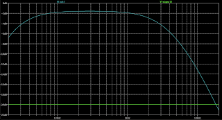
The frequency response is pretty flat, with a little roll-off on highs and lows, which is generally desirable in a guitar pedal.
It needs a little push before it starts to clip - and the output level is quite high. You can see the lower side of the wave has clipped on the output. Being a spice sim, this will not capture some other distortion that might be present simply due to part tolerances or slightly mismatched transistors.
Same again, but at 50% gain for both channels
The single channel running at 25% - but this is a LTspice model, so it may not actually run this clean. Depending on how you bias it, it may well be able to run clean - but why would anyone want to run this thing clean?


1 comment:
Delete if not appropriate but I saw the owner of eae pedals comment on a forum about the pedal pcb version…. This is from him
Mr. pedalpcb really borked the layout and PSU decoupling on this one. The charge pump is nestled in between a bunch of long runs to high impedance circuit nodes and is just blasting out noise everywhere. If you're able, tack a 100nF X7R cap from pin 8 on the charge pump to the nearest suitable ground (probably pin 3 but YMMV). And consider tacking another one across pins 4 and 8 on the TL072, as it has no local decoupling.
Also, if you find the lower gain tones to be overly muddy, try socketing C8 and swapping it out for a lower value cap. That value isn't correct on the build doc (it should be 270pF) but you can season to taste. I honestly have no idea where he got the 680pF value that is listed on the build doc.
Post a Comment