This is a rather interesting looking fuzz - one that I had overlooked until someone pointed it out to me (thank you Mister Hate). Before this, I was only aware of the MKIII-style fuzz that Sola Sound made for Carlsbro.
Despite having three transistors and being made in the mid-sixties in the UK, it is in no way related to a Tone Bender / the Maestro Fuzz-tone.
History: Link to Fuzzboxes (excellent site by the way)
Discussion: Link to FSB
CARLSBRO FUZZ-TONE | POINT-TO-POINT LAYOUT
So this is based on the original, with a few minor changes regarding placement. The layout on Freestompboxes did get me started, so credit to all those involved.
The original board is quite a mess (check the photos on fuzzboxes.org), which is why the transistors aren't shown. The transistors sit above the resistors and capacitors on the board.
ORIGINAL SCHEMATIC FOR THE FUZZ-TONE
I redrew it, as the original was making my brain hurt.
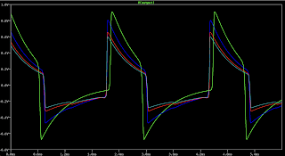
This kicks out a pretty mean-looking wave - I’ll attach some actual scope traces a bit later.
MODS FROM THE BREADBOARD
Jumper / remove the 100k resistor on the input
Remove 220k on output
Move attack pot 2 to V-
Increase input and output caps


20 comments:
I was about to build one of this on Vero just to hear it!
There's no original soundclips and only found 2 or 3 of new builds but I think it can be an interesting one. If all those mids are there, probably will become one of my new favourite vintage fuzz.
It looks pretty interesting, thanks for the tip about this one. I’ll breadboard it when I have time. Probably ripe for modding.
According to the old schematic I think the Volume pot is 25k, not 250k.
here's a vid of my NPN build, a very underappreciated circuit!! https://youtu.be/tmGCBB8piEM
Yep. I’ll fix that up. Think I was looking at the resistor next to it
Thanks GG. That’s a nice looking pedal - sounds good too.
Definitely, I need to try this one!
That sounds great. Did you stay within the recommended HFE ~50 Transistors? Or did you use something else?
I don't have a device to measure HFE but I auditioned the transistors in my little stash and ended up with a combination of two GT404 for Q1 & Q2 and an MP38A for Q3, which AFAIK are fairly low gain.
Just build it, but with a different layout that had a wrong capacitor in it. Thanks to your schematic I could easily solve the problem. Thanks!
Sounds great. I am a bit surprised that this fuzz wasn't more popular back in the days. I like that the attack knob is only for tone shaping while the guitar volume pot is the "real" attack pot. Also lots of different sounds are possible with this fuzz box. Worth to build in my opinion!
Thanks! I used GT404 as well and it works. Maybe I'll built a PNP version as well just to try different transistors.
Great - I hope to get to this on the weekend.
Right now I'm over hyped!
What transistors you finally used? Low gain/ high leakage? Because OC71 are a strange beast, they are usually low gain, but with leakage all over the place, I haver some Valvo with 0 leakage, and another ones unbranded with a leakage like OC75 usually have (well above 300ua).
According to the schem, at least Q1 and Q3 are leakage biased, isn't It?
I used low gain (40-50 HFE) with moderate leakage between 100-200 ua in all three positions. Works very well. But I am curious to try this circuit with low leakage PNP transistors. I read somewhere that this might work as well, maybe with trimpots. For instance the 10k going to Q3 could be a position for a trimpot.
I got it on the breadboard today. It’s pretty cool.
I used all OC71 and tested a few soviets as well. MP40 was closest to the OC71 - at least from my stash anyway.
This next week I am gonna try it with the mods for sure. When you say attack pot 2 to V-, you mean attack pot 2 to ground, isn't it?
Instead of attack 2 connecting to the emitter of q2, connect it to V- Basically becomes a bias resistor on the collector of Q3. Output level will increase dramatically
…and this thing is already loud!
Checking your schem, I see you removed the 10k from Q1C/Q2E. It can make much difference?
Not much at all - just reduces the range a little. It's better with it in, I'll amend the schematic.
Post a Comment