Friday, April 30, 2021

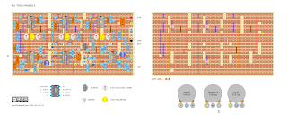
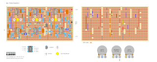
DEATH BY AUDIO: Fuzz War V2

The first version of the Death By Audio Fuzz War is notoriously tricky to clone - this is the second version, which is a modded Jumbo Tone Bender with a tweaked tone stack.  So, in other words, it's a modded Big Muff.


Schematic / build docs at PedalPCB


DEATH BY AUDIO FUZZ WAR V2 - VERO LAYOUT

DEATH BY AUDIO: Fuzz War V2, Guitar Effect Vero Layout


OFF-BOARD WIRING: Voodoo Labs Bypass System

I'm sure others have done it; however, this is commonly known as the Voodoo Labs bypass.  It's an interesting way of bypassing a pedal using a DPDT switch while including an LED indicator.  

Before 3PDT switches became available, designers had to choose between not true bypass with a LED or true-bypass without an LED (until the millennium bypass appeared, but that's another story).


Here's how it works:

PEDAL ON

The LED in the photo FET turns on, and the resistance of the FET drops down to a few hundred ohms - signal flows into the effect circuit, and the effect circuit output is routed to the output jack.

PEDAL OFF

The LED in the photo FET is off - the resistance of the FET increases to a few hundred megohms, blocking the signal from reaching the circuit.  The FET is also grounded.  So the signal sees a very large resistor to ground instead of a circuit.  The signal from the input jack is routed to the output jack. 


Or an even better explanation by R.G. Keen can be found here   


VOODOO LABS BYPASS SYSTEM

VOODOO LABS GUITAR EFFECT BYPASS SYSTEM


H11F3 PHOTO FET OPTOCOUPLER


Wednesday, April 28, 2021

COLORSOUND: Tone Bender Distortion

I did a point to point layout for this some time ago, which was actually my first post for this blog.  Full description via the link above.   

The Colorsound Tone Bender Distortion is more distortion than bender - there are zero similarities between a MKI, MKII or MKIII bender and this circuit. 


COLORSOUND TONE BENDER DISTORTION - VERO LAYOUT

COLORSOUND TONE BENDER DISTORTION - GUITAR EFFECTVERO LAYOUT STRIPBOARD LAYOUT FOR DIY FX


COLORSOUND TONE BENDER DISTORTION SCHEMATIC


Tuesday, April 27, 2021

Getting Started Building DIY Guitar Effects - What You Need

After a couple of posts about workbench tools etc, I thought perhaps it's time for a guide on where to start, as the internet is a big place full of opinions (now including mine).  

Sometimes it's hard to work out what one actually needs and why they are needed.  The idea of saving money by building your own pedals might soon disappear.  

THE BASICS REQUIRED FOR ANY DIY GUITAR FX BUILD

You can't finish a build without these;

  • a soldering iron - ideally one with a stand, replaceable tip and adjustable temperature in the 30-50w range.
  • a tip cleaner for the soldering iron.  I prefer a brass cleaning ball over the damp sponge.
  • solder - I use 0.71mm as I find it more precise than the 1mm variety.
  • flux - you will make mistakes that need to be unsoldered and re-soldered.  Without flux, this becomes a nightmare.  Watch this video if you are unsure about the wonders of flux.
  • a solder sucker or desoldering braid - see comment above; mistakes will be made.  Get a semi-decent solder sucker; the cheap ones are frustrating to use.
  • small pair of side cutters and a pair of pliers (which can double as wire strippers if you are really, really careful).
  • wire strippers.
  • jewellers screwdrivers.
  • small craft or Stanley knife.
  • spanners or a smaller shifting spanner.
  • a drill with a stepped bit if the enclosures you're using are not pre-drilled.
  • a magnifying glass - this is essential when starting out unless you have amazing eyesight.  This is for checking the solder side of vero boards to ensure that there are no solder bridges and, in some cases missed components.  It's easy to miss the leg of an IC socket on a crowded board.
  • for safety reasons, I probably should also mention an extractor fan.  Breathing fumes is not good for your health, probably quite bad.


TIME FOR TESTING YOUR CIRCUIT

Now, this is where it gets more interesting.  While the tools above will get a basic build done, if anything goes wrong, which it inevitably will at some stage, nothing there will help you test the circuit and find faults.  

This becomes really apparent when staring at your first build, wondering why it doesn't work, and not having a clue where to begin.

Basic test equipment;

  • a  digital multimeter - ideally one with a continuity tester (it beeps if things are connected).  An expensive multimeter is not required for guitar pedals. 
  • an audio probe (google it), unless you have an oscilloscope; this is the only way to follow the signal path in an attempt to find out where things have gone wrong.

When asking for help on forums / social media, the first thing people usually want is photos, a schematic/build docs and voltages on semiconductors.  And for a good reason too. 


NEXT STEPS

So now you have the basics sorted - things are going well, but you'd like to build something with germanium transistors, and the internet is yet again full of opinions and magical terms such as leakage and hfe.  

A multimeter just won't cut it when measuring germanium transistors, and for the most part, they don't do a very good job on silicon either.

There are two affordable choices;

  • a cheap multi-function tester - link to tester here.   These things are so cheap one could easily assume that they don't work.  Well they do, and for the money, they're great.  They test all sorts of things, including diodes, capacitors, resistors etc.

Either of these will tell you enough about your transistors to give you an idea of how they shape up.  Nothing beats testing them in the circuit, as I have often found that the transistors that are supposedly the 'wrong' transistors actually work just fine and sound great.


FURTHER DOWN THE RABBIT HOLE OF DIY EFFECTS

By now, you probably realise that making pedals may not have actually been a cheaper option than buying them after all.   So what next?

  • get a breadboard - why?  testing before committing to soldering becomes really obvious once you make a few pedals and start to test different components, fine-tuning them to suit your taste.
  • make a test rig - well, if you have a breadboard, you need a test rig right?  Everyone seems to have their own way of building a test rig - it's basically some form of enclosure that's easy to plug into your amp and attach the circuit to before boxing a circuit or while it's still on a breadboard.

BUT WAIT, THERE'S MORE

This is like the holy trinity of non-essential and potentially expensive tools.  They make the experience of building pedals just that much better - I think they are worth it if you have the space, money and intention to build a lot of pedals. 


MISCELLANEOUS EXTRAS 

  • a heat gun
  • extractor for solder fumes 
  • a work lamp
  • a small test amp that you don't care what happens to it, and/or a small monitor speaker
  • circuit clamp / strange third-hand clamp things 
  • a craft mat for cutting / working on
  • an old laptop / PC on your workbench, as you will be googling all sorts of things while you work out where you went wrong, or just for looking at layouts while you build them
  • and a bunch of other things that I can't remember right now, miscellaneous accessories that you will no doubt want along the way - I'm not even going to go near component storage


WHAT TO BUY & WHERE TO BUY PARTS FOR PEDALS

A common question and this is really too much to even try and answer, but I will leave you with some simple advice.

  • there's nothing wrong with using plain old 1/4watt metal film resistors - they're cheap and plentiful
  • greenie caps are fine, as are regular box caps and MLCC - like metal film resistors, there's nothing wrong with generic capacitors from a good quality supplier.
  • check the physical dimensions of capacitors before buying them, as you might mistakenly buy huge ones that don't fit (large voltage ratings can be a giveaway for this, especially for electrolytics)
  • don't buy JFETs, germanium transistors or germanium diodes off eBay from China - from my experience they are often fake
  • don't stress about having the exact part number for standard silicon transistors, as it hardly ever matters, so long as they're similar hfe (broadly low, medium or high gain)
  • Tayda is fine for most things
  • RS Electronics is great if you live in Australia.  I also resort to local stores that clearly have a lot of cheap imported parts sold at a hefty markup (Jaycar).  Altronics is a step up from Jaycar if you have one nearby.

Analog Signal Generator

This is my scruffy old analog signal generator that I picked up for $15 or $20.   I was actually surprised it still worked, given the apparent age.

If you don't have a signal generator and you see one going cheap, I'd suggest buying it if you are going to be building a few FX pedals.  While it doesn't have all the bells and whistles of the new digital ones, it just sits there and kicks out a nice sine or the occasional square wave - I never actually turn it off.

There's something to be said for having a reliable reference signal that never changes when fault-finding or testing pedals.  Given that I'm a big fan of oscilloscopes for testing pedals, it goes without saying that a good signal generator is a must-have (at least for me, anyway).

Analog signal generator for testing guitar effects pedals

I always run it at 440hz, and 130mv TRMS.  While 1kHz is usually considered a standard test wave, it annoys me after a while.  As you probably realise, 440hz is actually the A string of a guitar.  

I use sine waves for testing most things, except for filters or equalisation that actually need harmonic content to filter, which is where I use a square wave.  

Sine waves are great for testing any kind of overdrive/fuzz/distortion, as you can actually see the harmonics generated by distorting the wave, as sine waves have no harmonics by definition, just the fundamental frequency.


Monday, April 26, 2021

ZVEX: Fuzz Factory, Point to Point Layout

I haven't done a point to point layout for a while, and I also remembered that I've been meaning to make a Zvex Fuzz Factory for some time, but have never quite gotten around to it.  So here it is.   

I tried a Fuzz Factory using a different layout as one of my first guitar effects builds on vero, and it didn't work well at all - so much so that it ended up in the bin.  Maybe better luck this time with a bit more experience, and I have a couple of AC128s that could do with a home.  Think I tried some dodgy AC125s for the build that didn't work well, it was some time ago, so who knows what I did.


ZVEX FUZZ FACTORY - POINT TO POINT LAYOUT

ZVEX: Fuzz Factory, DIY Guitar FX Point to Point Layout


Wednesday, April 21, 2021

EARTHQUAKER DEVICES: Disaster Transport Jr

This is my first layout for a PT2399 based delay.  The Earthquaker Devices Disaster Transport Jr.   It's a pretty cool delay, with some very usable sounds - the addition of the tone control certainly helps, especially if you like something a little lo-fi sounding, or just as a method to filter out noise on longer delay times.

This is a large layout compared to some others available - I've built a couple from other layouts, and they're always a bit cramped for my liking.   


EARTHQUAKER DEVICES DISASTER TRANSPORT JR - VERO LAYOUT

EARTHQUAKER DEVICES DISASTER TRANSPORT JR - GUITAR EFFECT VERO LAYOUT


THE PT2399 CHIP

Want to know more - there's a really great analysis of the PT2399 chip on Electrosmash.  It's basically designed for karaoke machines.


TAILS MOD

I'll eventually get around to another version for keeping the delay tails when the pedal is bypassed.   The tails version basically runs as follows;

  • Input & output jacks wired directly to the board (as marked in & out) - the TL072 is acting as a buffer that is always in the circuit (goodby tru-bypass if that bothers you).
  • The foot switch is wired to break the signal going from the buffer to the PT2399 chip - so it stops signal reaching the delay chip, leaving the tails to finish naturally OR continue to self-oscillate if you have the feedback cranked.

MODULATION MOD - DISASTER TRANSPORT

Another mod is to add an LFO on a daughter board, so along with the tone control to filter the top end off the repeats, you can add something resembling tape warble. 

Modulation is the difference between the Disaster Transport Jr, and the regular Disaster Transport. 

The Keely Magnetic Echo is a very similar circuit to this one (like most PT2399 delays), with modulation.  So a good place to start for finding a LFO to add to the Jr.


VIDEO DEMO


Sunday, April 18, 2021

PETE CORNISH: ST-2, Modded (Simplified) Vero Layout

This is a simplified version of a Pete Cornish ST-2 (based on the Colorsound Overdriver).  I did the full layout, and it it kind of large, and double buffers are not for everyone.

So no buffers, and the power supply filtering is simpler.  I'm sure the proper Pete Cornish version is probably better, but if you prefer something smaller and simpler, this might be for you.

The full layout, including LTspice traces can be found here.   Please note that this is not actually an overdrive, it's really just a bass / treble control for tone shaping.


PETE CORNISH ST-2 - VERO LAYOUT - SIMPLIFIED VERSION 

PETE CORNISH ST-2 - GUITAR FX VERO LAYOUT - SIMPLIFIED VERSION DIY STRIPBOARD


PETE CORNISH: ST-2 (Colorsound Overdriver)

The Pete Cornish ST-2 is a Colorsound Overdriver with a few mods.  The ST-2 is intended to be a tone-shaper; it's not actually an overdrive.  So if you are looking for dirt, you have come to the wrong place with this one.  Although one can make a few tweaks to bring some dirt to this, but I'm not sure it would sound that great.  Could also make it a little hotter on the output by adjusting the gain of the op-amp, if you really want to push some tubes over the edge.

It has the usual Cornish buffer (two in fact) and an additional buffered/boosted output via an op-amp.   The power supply is a little over the top too.  Several feeds for different sections of the circuit.  

All of the extras make for quite a large vero layout, and after all it is really just a bass and treble control - I'll probably do a simplified layout at some stage with a single buffer, or maybe no buffer at all and a smaller power supply.  It should cut down the size and complexity quite a bit.

The wiring is for buffered bypass, which I don't mind.  It bothers some people... 

Schematic and tracing details can be found here, at Aion FX.  Instead of using this gigantic layout, maybe consider buying a board from Aion.  


PETE CORNISH ST-2 - VERO LAYOUT

PETE CORNISH ST-2 - GUITAR EFFECT VERO LAYOUT


ST-2 ON LTSPICE


ST-2 ON LTSPICE

As expected, there's a fairly standard bass/treble response

ST-2 ON LTSPICE - FREQUENCY RESPONSE


There's nothing to see on the output trace - no distortion on this one, purely tone shaping.

ST-2 ON LTSPICE - WAVE TRACE


CORNISH ST-2 VIDEO DEMO


Saturday, April 17, 2021

PETE CORNISH: SS-2, Vero Layout, Modded Buffer, SS-3 Values

Like the very lengthy title below suggest, it's a Pete Cornish SS-2 with mods.   After finishing the SS-3, they're almost the same, so I thought I would also do a SS-2 layout.


Changes

  • Swapped the Cornish buffer for a standard opamp based buffer
  • Ran the reference voltage through the spare opamp
  • Used a quad opamp instead of 2 x single op amps
  • Left SS-3 values throughout (which are mainly cap values and opamp gain)

PETE CORNISH SS-2 WITH MODDED BUFFER & SS-3 VALUES - VERO LAYOUT

PETE CORNISH SS-2 WITH MODDED BUFFER & SS-3 VALUES - VERO LAYOUT


PETE CORNISH: SS-3 Soft Sustain, Vero Layout, Buffer Mod

The Pete Cornish SS-3 is one of my favourite overdrives - so I thought I might make another one with a different layout and buffer.

Changes

  • Swapped the Cornish buffer for a standard opamp based buffer
  • Ran the reference voltage through the spare opamp
  • Used a quad opamp instead of 2 x single op amps


PETE CORNISH SS-3 SOFT SUSTAIN WITH BUFER MOD - VERO LAYOUT

PETE CORNISH SS-3 SOFT SUSTAIN WITH BUFER MOD - GUITAR EFFECT VERO LAYOUT


Sunday, April 11, 2021

EARTHQUAKER DEVICES: Grand Orbiter Phase Machine

The Grand Orbiter Phase Machine is a four-stage OTA phaser, with options for vibrato or phasing (a bit like a Univibe).

Not exactly a small board, but not too much to take on either.  MLC caps might be a good idea for some of the 1uf caps to save space. 

Currently unverified.  I have reviewed the schematic a couple of times, and two errors have been found and corrected, but still...  it's a huge board.  What could go wrong, right?


EARTHQUAKER DEVICES GRAND ORBITER PHASE MACHINE - VERO LAYOUT

EARTHQUAKER DEVICES GRAND ORBITER PHASE MACHINE - VERO LAYOUT


Saturday, April 10, 2021

MUSITRONICS: Mu-Tron Phasor II

A classic phaser from the mid-seventies - the Musitronics Mu-Tron Phasor II.  It has the same six-stage phaser as the Bi-Phase, with less happening in the oscillator section.  

This is the hardest layout I have ever done and took some time to finish and check...  including some time wasted after I started using a layout with errors in the oscillator section, which was very annoying.   

Being a six-stage phaser using DIY vactrols - what could possibly go wrong?  Unverified at present / build at your peril.

This should just fit in a Hammond 1590BB enclosure (landscape),  The dual rail power supply will need to be done on a separate board.  

I have not wired as per the original, as it was not true-bypass, and it has a relatively low input impedance of 390k.  If you really want to wire it up as the original, just check an old schematic, and you should be able to modify a layout to accomplish this.  


MU-TRON PHASOR II - VERO LAYOUT

MU-TRON PHASOR II - GUITAR EFFECT VERO LAYOUT


Pedal PCB values/schematic were used for the layout above, which is slightly different to one of the original schematics that I've seen.  This is running at +/- 9v.


MU-TRON PHASOR II - VERO LAYOUT - LFO WAVE SHAPE MOD

After looking in awe at the Mu-Tron Bi-Phase schematic, I realised that most of it are actually the same, or at least quite similar to the Phase II.

The mod below adds a sone / square wave selector.  I'm surprised they never included this on the original, as it's pretty easy to add (bearing in mind that this is currently an unverified layout).


MU-TRON PHASOR II - VERO LAYOUT V2


This layout is based on an original schematic, it's running at +/-12v, and it has very minor differences here and there - mainly in the LFO.  

MU-TRON PHASOR II - CALIBRATION

Note this refers to the older AC-powered unit, which is the layout directly above - please don't connect anything to mains power, or you may die in the process.  

In the instructions, it mentions changing R37 from 68k to 82k if there are flat spots on the waveform.  R37 is the resistor from Depth 2, connecting to pin 3 of IC5.  


MU-TRON PHASOR II VS BI-PHASE

A quick note on the main differences between the Bi-Phase and the Phasor II, as they are actually very closely related.  For starters, there are two phasers in the Bi-Phase - obviously.

Common
  • The six-stage phaser
  • The input section is basically the same, along with the feedback control
  • LFO oscillators have the same basic topology in terms of waveform generation
  • Sweep, Rate and Depth controls

Bi-Phase, Main Differences
  • LFOs have sine and square waves
  • LFO A rate can be controlled by an expression pedal
  • LFO B can be inverted or synced to LFO A
  • Additional routing controls, cause there are two phasers to play with - as an example, route Phaser A into Phaser B, giving a 12-stage phaser... 
  • Switching between Phaser A & B is controlled by a vactrol in the signal path of the output stage (audio section).  i.e. an optical switch.  When engaged, the switches increase resistance in the signal path to the point where audio does not pass.  

Wednesday, April 7, 2021

MUSITRONICS: Mu-Tron III

I've already built the Micro V, and it's a really cool-sounding envelope filter, so I thought I might try the Musitronics Mu-Tron III.  It's generally regarded as THE envelope filter of its day.  As much as I love a bit of fuzz, I really do enjoy sitting in a groove with an envelope filter running....  

Note read comments below - currently unverified. 

MUSITRONICS MU-TRON III - VERO LAYOUT

MUSITRONICS MU-TRON III - GUITAR EFFECT VERO LAYOUT


Same again, but bigger...   bit more room on the board.


Recommend that you check it against the schematic below if you plan to build this before I do.  I'll post photos etc once I have it made, or at least a progress report from the bench.   

The placement of the trimmer is a bit clumsy, but I think I will test some values and hopefully replace it with a standard resistor.  The trimmer is R23 on the schematic - see note re value.

Once (if ever) working, I'll need a suitable funky enclosure to fully release the seventies vibe.

ON THE BENCH

Seems to be partially working, but it's not fully wired up with all the switches etc yet.  I used the larger layout for this.

The homemade vactrol is working, although white heatshrink still lets light through.   Needs to be blacked out more - the case should take care of that, but it's not helpful trying test it like this.

It’s being very tricky to dial in, which may be the homemade vactrol, and/or the size of the trimmer on the LED.   Seems to have a very small spot where it works, but even then, the sweep is not great.    

Apparently, these are notoriously difficult to get going properly - maybe a Micro V is a better idea if you consider trying this.  


Suggested mods/notes to self to address issues 

1) bigger trim pot.  220k
2) change 180k resistor to 500k trimmer 

So still a work in progress - UNVERIFIED.


MUSITRONICS MU-TRON III - SCHEMATIC

MUSITRONICS MU-TRON III - SCHEMATIC
Note that the schematic above shows where to place an external control input for the envelope filter.


MUSITRONICS MU-TRON III - SCHEMATIC


The strange part labeled O805 is a single LED with dual LDRs.  It is not available to buy, so your options are make your own with LDRs and an LED, or try a couple of single optoisolators and see how that works.  

Google "R.G. Keen Neutron Filter" for more details on options.  

MUSITRONICS MU-TRON III vs EHX Q-TRON

As it happens the EHX Q-Tron is a direct progression of the Mutron III, albeit appearing over twenty years later.  They share a lot in common in terms of topology - perhaps due to the fact that they were both designed by Mike Beigel of Musitronics fame.

Monday, April 5, 2021

Bench Power Supply

Perhaps not often talked about in the world of guitar pedal building, as they’re kind of boring as all hell - the humble bench power supply.   So why am I bothering you with this?

Apart from being able to dial in most voltages that I need, a bench power supply is actually a handy tool in other ways.  As soon as I turn it on and see the current fluctuating or pulling more current than it should be, I know I have a problem with the circuit.

They’re also safer than using a battery, as there’s actually potential for batteries to get really hot and explode if you have a short on the supply and leave them for some time.  

So if you don't have one and are wondering what's the point when a wall-wart or a 9V battery will do for most things...   well, maybe consider one if you see it going cheap.


bench power supply for testing guitar pedal circuits


Sunday, April 4, 2021

MXR: M-103 Blue Box

The MXR M-103 Blue Box is a sub-octave fuzz (two octaves down).  It's not a clean sub-octave either, pretty dirty really, well it's a fuzz...  kind of synthy on some settings.

Might want to check how many 56k resistors you have before starting this.  


MXR BLUE BOX - VERO LAYOUT

MXR BLUE BOX - GUITAR EFFECT VERO LAYOUT STRIPBOARD LAYOUT


BLUE BOX OCTAVE MOD

Same again, but with the octave mod - this provides the option to switch between just one octave below or the standard two octaves below.  Very handy; I would recommend this over the stock version.

Another mod is replacing the 10n cap to ground on the output with a smaller cap, or remove it altogether, or putting it on a switch for the best of both worlds.  

The 10n does shave a lot of high frequencies off (see scope traces below) - even on a switch you may want a smaller cap.  


BLUE BOX ON THE SCOPE / FFT

Signal   440hz sine wave, approx 130mv TRMS

Out of the IC, on the 56k / 10k divider to drop the level to a reasonable amount (massive signal straight off the pin) - as you can see, it's pretty much a square wave now.


Blend set to max octave, switch on 2 octaves down, no cap across the output to ground.

 
Blend set to max octave, switch on 2 octaves down, 10n cap across the output to ground.


Blend set to max octave, switch on 1 octave down, no cap on output to ground.


Blend set to max octave, switch on 1 octave down, 10n cap on output to ground.


M-103 BLUE BOX VIDEO DEMO


Thursday, April 1, 2021

KORG: MS-20 Filter, Tim Escobedo Version

If the other MS-20 filter is all too much, maybe this will be easier.  It's Tim Escobedo's adaptation of an MS-20 style filter for guitar, just using the an LM13700 and running at 9v.  

KORG MS-20 FILTER - TIM ESCOBEDO VERSION - VERO LAYOUT


KORG MS-20 FILTER - TIM ESCOBEDO VERSION - VERO LAYOUT