Saturday, November 28, 2020

D*A*M: Tone Bender TB-00, 0.15" Vero Layout

The D*A*M TB-00 Tone Bender is Vox Tone Bender with a minor variation on the original.  

Strangely the input capacitor on this layout is hidden under the board, so I guessed the value.  Likely to be the same as the original (150n) or a 220n like the '66.  No idea why it's hidden - some were under the board on originals, so maybe that's why?  

Anyways, had me confused for a while trying to work out what was going on while working on the layout.


D*A*M TONE BENDER TB-00   |   0.15" VERO LAYOUT

D*A*M TONE BENDER TB-00


TB-00 VIDEO DEMO


D*A*M: Zoot Unit ZU-65, 0.15" Vero Layout

Another D*A*M layout that I traced from photos is the Zoot Unit ZU-65, which is a Zonk Machine....   

I did see a couple of photos with what appeared to be a slightly larger input, but I’m not entirely sure about this.


D*A*M ZOOT UNIT ZU-65   - 0.15" VERO LAYOUT

D*A*M ZOOT UNIT ZU-65 - DIY GIUITAR FX VERO LAYOUT


Saturday, November 21, 2020

Fuzz Machine: Unbranded Ibanez Standard Fuzz

The Fuzz Machine is clearly an unbranded Ibanez No 59 Standard Fuzz.

I occasionally buy a few parts from a retired guy with a shed full of vintage electronics and components, mostly valves and radio gear.  A while back, he mentioned that there were a couple of pedals buried somewhere in the shed.  

I was picking up some transistors from him today, and he'd managed to track the pedals down.  He was kind enough to let me have a look at it, to test before he sells - he wanted to make sure it worked first and wasn't happy with a bench test. 


FUZZ MACHINE  (AKA IBANEZ STANDARD FUZZ)

I took the opportunity to open it up and record voltages and scope results for future use, as I have been meaning to make the Ibanez Standard Fuzz for a while but have not got around to it yet.  

Apart from a few small cobwebs, it's spotless inside, the battery compartment is in good shape, and the faders feel fine for their age. 

And it sounds pretty much as expected...   it does what it says on the box.   Reassuringly, it sounds a lot like the Super Fuzzes that I've made.  Always good to get a side-by-side comparison - I only wish mine looked half as cool as this.  

Fuzz Machine - Ibanez Standard Fuzz pedal


Fuzz Machine - Ibanez Standard Fuzz pedal


Fuzz Machine - Ibanez Standard Fuzz pedal - guts

Fuzz Machine - Ibanez Standard Fuzz pedal - circuit board

Fuzz Machine - Ibanez Standard Fuzz pedal - circuit board

Fuzz Machine - Ibanez Standard Fuzz pedal - circuit board


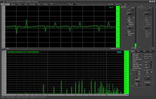
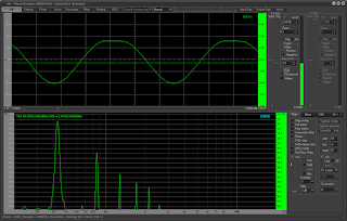
WHAT DOES THE FUZZ MACHINE LOOK LIKE ON THE SCOPE ?

Signal:  Sine wave, 440hz, approx 130mv
Fuzz & volume on 100%
Battery 8.95v

Notch filter on
Fuzz Machine - Ibanez Standard Fuzz pedal - SCOPE / FFT


Notch filter off

Fuzz Machine - Ibanez Standard Fuzz pedal - SCOPE / FFT


First Stage, SK30 JFET

Drain        6.0v
Source     0.88v

Fuzz Machine - Ibanez Standard Fuzz pedal - SCOPE / FFT


Second Stage, C828 splitter, collector and emitter

Collector    5.0v
Base          4.0v
Emitter       3.5v

Fuzz Machine - Ibanez Standard Fuzz pedal - SCOPE / FFT

Fuzz Machine - Ibanez Standard Fuzz pedal - SCOPE / FFT


Third stage, C828, long tail pair collectors

Collector    4.0v
Base          1.1v
Emitter       0.5v

Fuzz Machine - Ibanez Standard Fuzz pedal - SCOPE / FFT


Last stage, C828

Collector    6.4v
Base          0.88v
Emitter       0.28v


Diodes
1N60 Germanium
Forward voltage 0.37v

D*A*M: Buzzotron, Tag Board Layout

The Buzzotron is almost identical to the original layout for the Buzzaround, which was also built on tag board. 

It sounds pretty good - a bit low on output on some settings, but otherwise a very nice sounding MKIII variant.  

The Buzzotron only has minor differences to the Buzzaround - bias resistors on the base of Q1 are different, and it also has a 220pf capacitor across the base and collector of Q1 like a normal MKIII - this is not present on Buzzarounds.

The tone control may have a different corner frequency on the treble side, but this is entirely dependent on what Buzzaround schematic you compare it against, as I've seen two different versions.   One of the only components that I can't see in photos of the Buzzotron is the small capacitor hiding behind or sometimes under the 220n capacitor. I have seen a 1n, on a Buzztronix ZZ.1, and this is the stock value of a Buzzaround, so I think it's a safe bet.

Buzzaround    15 kHz      10k resistor, 1n capacitor
Buzzaround     3.7 kHz    43k resistor, 1n capacitor

Buzzotron        15 kHz    10k resistor, 1n capacitor      (early version)
Buzzotron        4.8 kHz    33k resistor, 1n capacitor     (later version, this increases the level and gives a better sweep, but it does lose a bit of the original flavour)


I've seen Buzzotron vero layouts using a 33k resistor with a 4n7 capacitor - which equates to 1 kHz.   Not sure where they got these values from, but 1 kHz seems low compared to 15 or 4.8 kHz.  I haven't found a photographic reference, schematic or another source to confirm this (not to say that it doesn't exist, maybe I just haven't found it yet).

D*A*M BUZZOTRON - FIRST TAG BOARD LAYOUT

D*A*M BUZZOTRON - ORIGINAL TAG BOARD LAYOUT


LATER BUZZOTRON TAG BOARD LAYOUT

D*A*M BUZZOTRON - LATER VERSION TAG BOARD LAYOUT


Basically the same, but with some minor tweaks.  The later version has a 33k resistor paired with the 1n capacitor on the output (lowering the frequency of the highness filter), and the resistor to the Balance pot is 27k instead of 22k that's found on the earlier model.


Anyone that can read resistor values obviously doesn't need this and might wonder why I bothered - but I'm not yet one of those people, so I do need it.

SCHEMATICS


BUZZOTRON ON THE BENCH

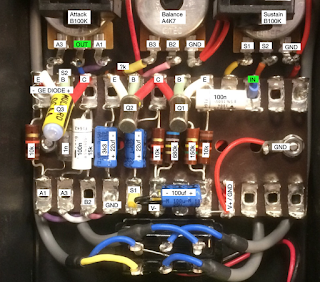
Metal oxide resistors, tropical fish & styroflex caps, axial electrolytics, OA7 germanium diode, and OC45 transistors.  Technically an OC45 should not work very well in Q3 of a Tone Bender MKIII style circuit - not enough leakage and a relatively low hFE.  I think it sounds great here... I preferred it over everything except an OC44, but I only have two of those, so saving them for something else.     

I did swap the 10k on the treble side to a 33k, and I like it, but I think I might also try an internal trimmer to fine-tune the frequency.  The 33k is great in that it has more output, but it also lost something compared to the frequency content of the 10k.


FINAL

So I added a trimmer to tune the treble side, which is handy but hardly essential.  If you don't have a trimmer, I would recommend breadboarding this with a 10k, 22k, and 33k on the forming the high-pass filter on the treble side to fine-tune this to tase.


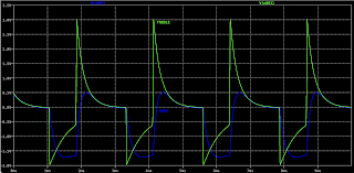
ON THE SCOPE / FFT

Signal:  440hz sine wave, approx 130mv
 
Bass


Treble  note:  2n2 capacitor used instead of 1n


50/50 mix Bass / Treble


Tuesday, November 17, 2020

D*A*M: Dizzytron ZZ.2

I thought it was another D*A*M variation on the Buzzaround, but it turns out that it's actually an Elka Dizzy Tone, which is still very much a Buzzaround (as pointed out by Anders, AKA fuzzhead, see comments).

There's one resistor that I could not see the value of; it's likely to be 18k based on Elka values, but like most things relating to biasing germanium transistors, test it and see what works best with the parts available to you.  

Differences to the Buzzaround

  • The pair of bias resistors on the base of Q1 is odd values
  • 22u caps instead of 4u7
  • 250k rev log for Sustain
  • 1m or 100k for Attack
  • 4k7 for Balance


D*A*M DIZZYTRON ZZ.2   |  TAGBOARD LAYOUT

D*A*M DIZZYTRON ZZ.2


Some links are not shown - for example: Q1 emitter connects to Q2 base.  If you're building on tag, I'm assuming you know what connects where on a Tone Bender MKIII-style circuit.


Monday, November 16, 2020

D*A*M: FZ-673 Fuzz, 0.15" Vero Layout

I've already made a point-to-point layout for this, and as I'm currently on a 0.15" D*A*M vero roll, I thought, why not...   and it's a Zonk Machine with tweaks.

Remarkably similar to the original D*A*M layout, I did move the output from the board a little and swapped pins on the swell pot to a more standard configuration.  If you want to change it, I'm sure you'll work it out.

The D*A*M layout has a standing axial capacitor, which doesn't really work on DIYLC, so I used a standard cap and added polarity markers.


D*A*M FZ-673 FUZZ -  0.15" VERO LAYOUT

D*A*M FZ-673 FUZZ - VERO LAYOUT DIY STOMP


Sunday, November 15, 2020

D*A*M: Super Bee SB-68, 0.15" Vero (incomplete trace)

The D*A*M Super Bee SB-68 was mentioned as something that had not been traced yet, which made me curious.  I looked at a few photos and found that there are two versions.  One with OC82s and one with OC78s.  Some very slight differences, but otherwise, a MKII Tone Bender cramped onto a smaller board to fit the enclosure.

I still haven't been able to spot the value of the electrolytic capacitors on the input and on the Attack pot. These should not make a significant difference to the sound.  

If you have any more info or disagree with the values shown, please let me know in the comments.  Components with a red outline are assumed based on other TBs.


D*A*M SUPER BEE SB-68 - VERO LAYOUTS

OC82 VERSION

  • No 10n cap to ground on Q1 base
  • 100k bias resistor on Q2 collector
  •  8k2 / 560 ohm bias resistor combo on Q3
  • The resistor hiding under the electrolytic near the output cap is most likely the same value as an Italian TB


D*A*M SUPER BEE SB-68 - GUITAR EFFECT VERO LAYOUTS


OC78 VERSION

  • 10n cap to ground on Q1 base
  • 47k bias resistor on Q2 collector
  • 8k2 / 1k bias resistor combo on Q3 collector
  • There doesn't appear to be a resistor involved with the attack pot, like on the Italian TBs (none that can be seen anyway)


D*A*M SUPER BEE SB-68 - GUITAR EFFECT VERO LAYOUTS


Saturday, November 14, 2020

D*A*M: Meathead M-27, 0.15" Vero Layout

It's a silicon Fuzz Face with an input cap blend - the D*A*M Meathead M-27, or the Meathead Deluxe.    

I copied the D*A*M layout from photos on Stompboxes UK and the usual pics on Reverb.  Strangely, the same issue I had on another layout - in all photos, the yellows on resistors looked green...  go figure.   

I suggest testing the 12k resistor before committing, as I have seen schematics and layouts using different values - 18k as an example.  

Some also have different values for the input and output capacitors, I've used values that I have seen in photos, and where I could not see values, I've used values from schematics and layouts by others (there's no shortage out there).


D*A*M MEATHEAD M-27 - VERO LAYOUT

D*A*M MEATHEAD M-27 - VERO LAYOUT


COLORSOUND: Fuzz Box

They don't come much more straightforward than this - said to be a Dick Denney design, the Colorsound Fuzz Box is a one-knob silicon fuzz face with a couple of value tweaks, but other than that, you know what you're getting here.   

This circuit is also found in the Vox V1141 Super Beatle solid state amplifier.

The layout below is the D*A*M / Macari's reissue, which is a great way to use up the little bit of vero left over from making other circuits.

COLORSOUND FUZZ BOX   -   0.15" VERO LAYOUT

COLORSOUND FUZZ BOX VERO LAYOUT

There's a few comments below regarding values - yes, they can vary a bit in the wild.   I think the different Macari's releases have slight tweaks to some resistor or transistor values.   From what I gather, this is normally the bias resistors on Q2 (2k2 and 82 ohm as shown above).  

There's also a bit of debate on the topic at FSB


The Colorsound Hammer House Fuzz Box uses what looks to be 5k6 and a 270 ohm resistor, so there is some room for movement or experimentation in this area.  I've certainly needed to change values occasionally to get the best results out of some vintage RCA silicon transistors that I was using.

Increasing the 82 ohm resistor lifts the output a bit.  With the 82 it's a bit above unity running full tilt.   


Same again but with a 120 ohm resistor - you can see it has a bit more beef now compared to the input signal, despite only having an extra 38 ohms of resistance.


Below is the Hammer House version - even hotter again


Wednesday, November 11, 2020

D*A*M: Fuzz Sound FS-77, Tag Board Layout

I couldn't find a layout for the FS-77 anywhere, but I did find some photos online, so I decided to try and trace it back in November 2020.  I thought I had it, but when I looked at it again recently, I noticed the input didn't look right.  The caps were the wrong way around for an input blend...  hmmm.  If it's not an input blend, what is it?

So I went looking for more information, and recently someone was kind enough to share some photos with me (you're a legend), which completed the picture - I was a bit lost without the additional photos, and had mistaken the blend pot for an input blend, which is not uncommon on D*A*M designs.


THE BONES OF THE FS-77

So what is the FS-77?  Like most Fuzz Sounds, it's a Tone Bender MKIII with tweaks.  

  • The collector resistor on Q1 & Q2 is only 4k7, as opposed to 10k
  • 4.7uf input cap, with a 10n to ground
  • Usual 220pf cap across collector and case of Q1 is 47pf
  • Sonically the biggest change is the tone & blend controls, which are based on a Big Muff tone stack.  The blend is a kind of a mid-range control, based on the same idea as the AMZ presence control.  The blend pot changes the high-pass filter cut-off, which forms one half go the BMP tone stack.

D*A*M FS-77 FUZZ SOUND SCHEMATIC


D*A*M FS-77 FUZZ SOUND SCHEMATIC


ASSUMPTIONS

There are some component values that I've not seen, all other values have been seen on photos.

  • Fuzz, tone and volume have been assumed based on normal tone bender values used by D*A*M
  • Initially I had a 25k pot for blend, but after testing it, I've landed on 50k. Try some different values, maybe you prefer a 25k - the 50k just has a slightly wider range.   Being a BMP tone control, it's easy enough to tune to your personal taste, even if the stock FS-77 values are a little unfamiliar.
  • The 220n between the tone and volume might be a different value - looks the same as the 220n on the board, and is large enough to not impact the frequency response after the tone control

TONE CONTROL

Despite being a BMP based tone control, they're not even close to typical BMP values 

It does allow a mid hump, as well as a bit of a scoop on some settings.


Bass, low-pass filter

220k & 2.2n = 329hz


Treble, high-pass filter

25k pot:     10n cap & 1.5k - 26.5k = 600hz to 10.6khz sweep

50k pot:     10n cap & 1.5k - 51.5k = 300hz to 10.6khz sweep


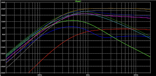
LTspice - tone & blend swept in values from 1, 50 & 100% (50K blend pot)


ON THE BENCH 

It works...   it gives you some classics tone bender MKIII tones, and then some more modern sounds as a result of the tone control.  

The blend provides a nice sweep, and works well with the tone control.  There’s a lot of useable tones in there.  I prefer the 50k pot as you get more range.  

I ended up using a wider piece of tag board as I'm going for a landscape layout in the enclosure.


D*A*M FUZZ SOUND FS-77 - TAG BOARD LAYOUT

D*A*M FUZZ SOUND FS-77 - TAG BOARD LAYOUT


Note: NKT213 transistors also used

D*A*M FUZZ SOUND FS-77 - VIDEO DEMO

I believe this is the only video demo out there.  You get an idea of the sound, but the pedal stays on one setting throughout, so it doesn't provide any ideas on the range.


Tuesday, November 10, 2020

Sola Sound: Tone Bender MKII Professional Hybrid, 0.15" Vero Layout

This hybrid Tone Bender MKII is a more budget conscious offering from Sola Sound (Macari's) via David Main of D*A*M and it uses NPN transistors, which is a bit of a bonus.

SOLA SOUND TONE BENDER MKII PROFESSIONAL SILICON HYBRID - VERO LAYOUT

SOLA SOUND TONE BENDER MKII PROFESSIONAL SILICON HYBRID - VERO LAYOUT

Watch out for the hard to spot cuts under the 470 ohm and 100 ohm resistors.


D*A*M: Head Buzz

And I thought some of my layouts were big...   The D*A*M Head Buzz is a standard Fuzz Face clone made in limited numbers for a Japanese Guitar shop.   


D*A*M HEAD BUZZ - VERO LAYOUT

D*A*M HEAD BUZZ - VERO LAYOUT - GUITAR FUZZ PEDAL


Sunday, November 8, 2020

D*A*M: Red Rooster Booster

I've already done a point to point layout for the D*A*M Red Rooster Booster (which I love by the way), but as I'm on a run of D*A*M layouts today, I thought I might do this one too.  Like the rest, this is not my layout; it's a close copy of the D*A*M layout.  If you want to stay true to the look, hide the jumper under the board.

This is the PNP version, which can easily be changed to NPN if you prefer by flipping the electrolytic caps.  

I noticed in one photo, a resistor to ground from the 10n output cap.  Maybe there was some pop that needed to be dealt with?   Anyway, squeeze that in between the two electrolytics if you need or want to try that.  I couldn't make out the value...  1meg has worked for me in the past.

Try setting the trimmer to 3.9k to start with, as that's the standard value for a Rangemaster Treble booster, which this of course is a variation on.  Someone once asked David Main about bias voltages - he suggested 6.66v - no doubt a little joke on his part, but it will get you close.  This is one that you can happily bias by ear; it seems fairly forgiving, at least it was on my other build. 


D*A*M RED ROOSTER BOOSTER - VERO LAYOUT

D*A*M RED ROOSTER BOOSTER - VERO LAYOUT


D*A*M: Greasebox GB-88


This is an interesting one - I started this layout thinking the D*A*M Greasebox GB-88 would just like the others.  It mostly is, but it gets a little odd in the tone section.  When I was looking at photos of the GB-88 to copy the D*A*M layout, I noticed that there's no resistors to ground from the caps that connect to the tone pot - well none that I can see from the photos anyway, so maybe they have been placed under the board? There's also a large resistor across pin 1 & 2 of the volume pot.

I’ve pulled the layout I had posted, as there was too much guess work involved.   

But if you want to take a stab at one, build a MKIII with a 22n input cap and a 100n coupling cap going to the fuzz pot.   Filter caps are 220n and 4n7.

That’s as much as I could make out.


Saturday, November 7, 2020

D*A*M: Greasebox GB-83, 0.15" Vero Layout

This is a departure for D*A*M - for one, it's silicon, and two, it's a regular negative earth circuit.   So the Greasebox 83, is quite different to the other Greaseboxes.

This is not my layout; this is about the same as the D*A*M layout from what I've managed to work out by looking at pics - I may be a bit off, yet to build this one, so see what happens.  It looks correct from what I can see.  Feel free to drop me a line via comments if you think I have something wrong.  

D*A*M GREASEBOX GB-83   |   0.15" VERO LAYOUT

D*A*M GREASEBOX 83 - VERO LAYOUT FOR DIY STOMPBOXES


D*A*M: Greasebox 80, 0.15" Vero Layout

The D*A*M Greasebox is kind of a hot-rodded Tone Bender MKIII.  It just takes a 100n cap straight off the collector of Q3 and runs to the volume instead of passing through the usual Tone Bender tone control.

This is not my layout; this is about the same as the D*A*M layout from what I've managed to work out by looking at pics.   


D*A*M GEASEBOX 80 -   0.15" VERO LAYOUT

D*A*M GEASEBOX 80 - VERO LAYOUT GUITAR EFFECT


D*A*M: Fuzzsound Black on Black, 0.15" Vero Layout

I've officially run out of things to say about D*A*M Tone Bender variations.  

The Black on Black has a larger coupling capacitor and a larger capacitor on the treble side of the tone pot, resulting in a lower cut-off on the high-pass filter.  It will have a far more meaty mid-range than a regular MKIII.


D*A*M FUZZSOUND BLACK ON BLACK  -  0.15" VERO LAYOUT

D*A*M FUZZSOUND BLACK ON BLACK - GUITAR EFFECT VERO LAYOUT