Such a lengthy heading... I've been waiting to find out what was going on with this one, and it has recently been traced on the Pedal PCB forum. There's also a great back story here, with some info on the Zener diode.
The schematic can also be found via the Pedal PCB link above.
There are other earlier versions, including a PNP version using an OC75. The OC75 version is very close to the OC140 version - although there's no diode involved in biasing the collector, just a 4k7 resistor (and obviously some different transistors on Q1 / Q2). A couple of odd value resistors, like a 10ohm on the emitter of Q2. I'm pretty sure I'm reading it correctly, but...
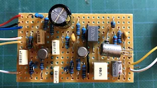
The PCB is a Jumbo Tone Bender board with modified parts/values.
COLORSOUND HYBRID TONE BENDER (2018 EDITION) - STANDARD VERO LAYOUT
note: V3 germanium diode polarity reversed, fuzz pot changed to A100k
I'll get around to cleaning up the connections at some point, as they are a bit rough and will also add another diode for polarity protection - this was a quick solder job for testing.
It works.... sounds like a Tone Bender too. Not a direct replication of the sound of a MKIII / MKIV, but the flavour is there.
I had to make a few substitutions as I did not have all the parts as per spec.
- 5.1V zener diode, instead of the 4.7V (bear in mind the actual value has yet to be confirmed)
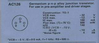
- AC127 instead of the OC140 - it's quite leaky, with a gain around 100
- AT426 instead of the BC107
- 100n instead of 10n, just because I wanted to, and it has been seen in earlier versions
TONE POT SWEEP
The PNP version uses tropical fish capacitors, using a 47n cap instead of 33n, resulting in a slightly different sweep, with less of a dip in the mids.
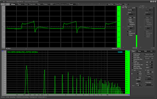
ON THE SCOPE / FFT
Input signal: 440hz sine wave, approx 130mv TRMS
Q1 Collector (AT426)
Fuzz set to 100%
Q2 Collector (BC109C)
Fuzz set to 100%
Q3 Collector (AC127)
Fuzz set to 100%
C 1.7V (Traced pedal read 2.5V with OC140)
B 0.1V
E 0.0V
Bass
Treble
Tone 50 / 50 Mix


